Toyota HiAce (2004-2013)

The fifth-generation Toyota HiAce—marketed under various names such as Toyota Commuter (Thailand), Toyota RegiusAce (Japan), Toyota Quantum (South Africa), and Toyota Ventury (Thailand)—was launched in 2004 under the model code H200. This pre-facelift version was produced until 2013 and gained a strong reputation worldwide for its reliability, spacious cabin, and versatility, making it a popular choice for both commercial and passenger use.

In this article, you will find fuse box diagrams for the Toyota HiAce covering model years 2004, 2005, 2006, 2007, 2008, 2009, 2010, 2011, 2012, and 2013. These diagrams help identify specific fuses and relays related to the vehicle’s electrical systems, making it easier to troubleshoot or replace components.

What’s Included:

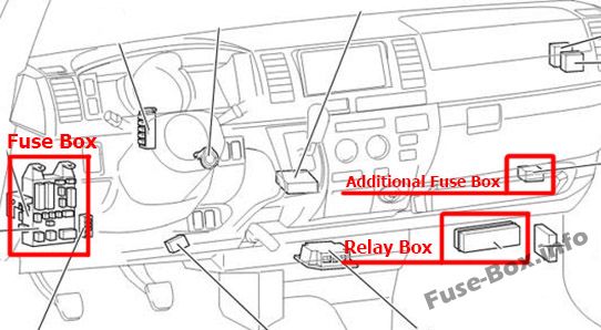
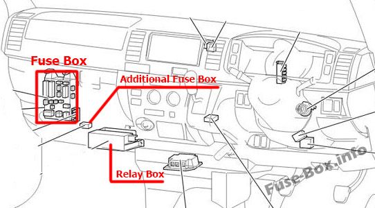
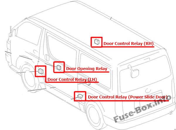
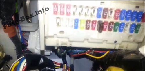
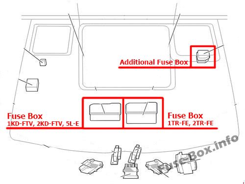
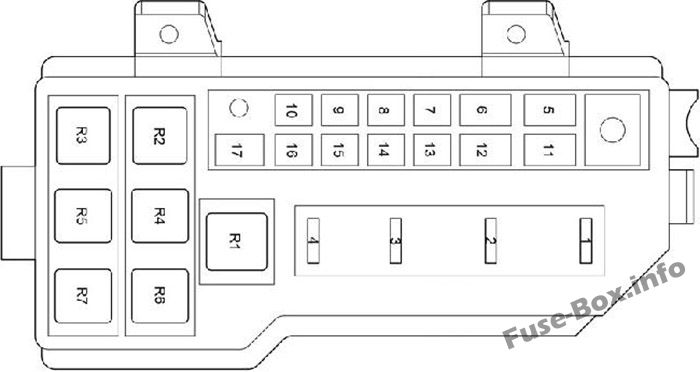
  • Fuse Box Diagrams – Visual layouts detailing the arrangement of fuses and relays.
  • Fuse Panel Locations – Guidance on where to locate fuse panels inside the vehicle.
  • Fuse Assignments – Descriptions of what each fuse and relay controls, aiding diagnostics and repairs.

Whether you’re resolving an electrical problem or performing preventive maintenance, this reference will assist you in managing the fuse and relay system of your Toyota HiAce H200 (2004–2013) efficiently.

Passenger Compartment

Fuse box locationd

Left-hand drive vehicles

The location of the fuses in the passenger compartment (LHD): Toyota HiAce (2005-2013)

Right-hand drive vehicles

The location of the fuses in the passenger compartment (RHD): Toyota HiAce (2005-2013)

The fuse box is located under the instrument panel, under the cover.

The location of the fuses in the passenger compartment: Toyota HiAce (2005-2013)

Fuse box diagrams

Instrument panel fuse box diagram: Toyota HiAce (2005-2013)

Assignment of the fuses in the Passenger Compartment

NameAmpCircuit
1
2ACCL INT LCK25
3WIP25Windshield wipers
4RR WIP-WSH15Rear window wipers and washer
5WSH20
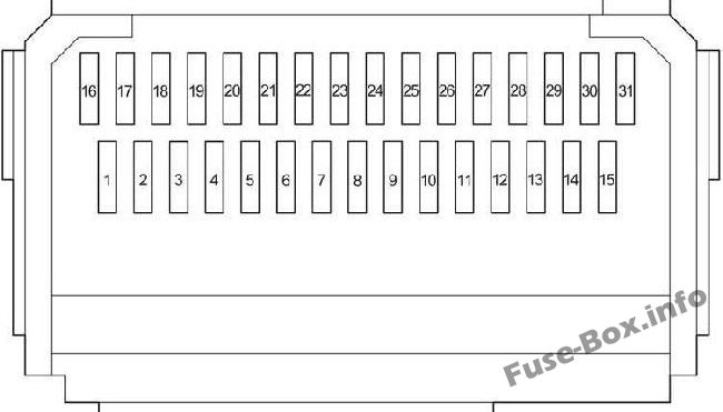
Window wipers and washer, rear window wipers and washer
6ECU-IG7.5Air conditioning system, automatic transmission shift lock control system, anti-lock brake system, sliding door closer system, multiport fuel injection system/sequential multiport fuel injection system, multiplex communication system
7GAUGE10Gauges and meters, rear turn signal lights, stop/tail lights, back-up lights, rear window defogger, electric cooling fans, charging system, air conditioning system, power windows
8OBD7.5On-board diagnosis system
9STOP10Rear turn signal lights, stop/tail lights, back-up lights, high-mounted stoplight
10
11DOOR30Power windows, power door lock system
12RR HTR15Air conditioning system
13
14FR FOG10 / 15Front fog light
15AM130All components in “ACC”, and “CIG” fuses, starting system
16TAIL10Front position lights, rear turn signal lights, stop/tail lights, back-up lights, license plate lights, clock, instrument panel light, multiport fuel injection system/sequential multiport fuel injection system
17PANEL10Instrument panel light
18A/C10Air conditioning system
19
20
21
22
23CIG15Cigarette lighter
24ACC7.5Power rear view mirror, automatic transmission shift lock control system
25
26ELS10Multiport fuel injection system/sequential multiport fuel injection system
27AC100V15
28RR FOG15Rear turn signal lights, stop/tail lights, back-up lights
29
30IGN15Multiport fuel injection system/sequential multiport fuel injection system, electronic throttle control system, SRS airbag system
31MET IGN10Gauges and meters

Login or Register to view this content
Instrument panel fuse box diagram: Toyota HiAce (2005-2013)

NameAmpCircuit
1POWER30Power windows
2DEF30Rear window defogger
3
Relay
R1Ignition (IG1)
R2Heater (HTR)
R3Flasher

Login or Register to view this content

Relay Box

The relay box is located under the instrument panel, behind the cover.

Passenger Compartment Relay Box: Toyota HiAce (2005-2013)
Passenger Compartment Relay Box (diagram): Toyota HiAce (2005-2013)

Passenger Compartment Relay Box

NameAmpCircuit
1HEAD LL15
2HEAD RL15
3HEAD LH15Left-hand headlight
4HEAD RH15Right-hand headlight
5ST7.5Starting system, multiport fuel injection system/sequential multiport fuel injection system, gauges and meters
6A/C NO.37.5Air conditioning system
7
Relay
R1
R2Headlight (HEAD)
R3
R4Starter (ST)
R5(OSV)
R6
R7Front fog light (FR FOG)
R8Air conditioner compressor clutch (MG CLT)
R9(INJ/IGN)

Login or Register to view this content

Engine Compartment

Fuse box locations

The location of the fuses in the engine compartment: Toyota HiAce (2005-2013)

Fuse box diagrams

Fuse Box in the Engine Compartment (location): Toyota HiAce (2005-2013)
Fuse Box in the Engine Compartment (diagram): Toyota HiAce (2005-2013)

Assignment of the fuses in the Engine Compartment

NameAmpCircuit
1A/F151TR-FE, 2TR-FE: Multiport fuel injection system/sequential multiport fuel injection system
1EDU251KD-FTV, 2KD-FTV, 5L-E: Multiport fuel injection system/sequential multiport fuel injection system
2HAZ-HORN15Horns, emergency flasher
3EFI201TR-FE, 2TR-FE: Electronically controlled fuel pump, multiport fuel injection system/sequential multiport fuel injection system, electronic throttle control system
3EFI251KD-FTV, 2KD-FTV, 5L-E: Electronically controlled fuel pump, multiport fuel injection system/sequential multiport fuel injection system, electronic throttle control system
4
5ALT140All components in “MAIN3”, “FAN1”, “FAN2” and “GLOW” fuses
5ALT150Refrigerator Van: All components in “MAIN3”, “FAN1”, “FAN2” and “GLOW” fuses
6A/PUMP501TR-FE, 2TR-FE: Emission control system
6GLOW801KD-FTV, 2KD-FTV, 5L-E: Engine glow system
7MAIN 350All components in “A/F”, “HAZ-HORN” and “EFI” fuses
8FAN 250Electric cooling fans
9FAN 3301KD-FTV, 2KD-FTV, 5L-E: Electric cooling fans
10FAN 150Electric cooling fans
11PTC1501KD-FTV, 2KD-FTV: PTC Heater
12MAIN4120All components in “WELCAB”, “AC100V”, “RR FOG”, “RR HTR”, ”OBD”, “STOP”, “AMI”, “DOOR”, “FR FOG”, “PWR”, “DEF”, “ELS”, “TAIL”, “PANEL”, “ECU-IG”, “WIP”, “WSH”, “GAUGE”, “RR WIP-WSH”and “A/C” fuses
13
14HTR40Air conditioning system
15
16RR CLR30Rear air conditioner
17PTC2501KD-FTV, 2KD-FTV: PTC Heater
Relay
R11TR-FE, 2TR-FE: Rear air conditioner (RR CLR)
R21KD-FTV, 2KD-FTV, 5L-E: Engine glow system (GLOW)
R31KD-FTV, 2KD-FTV, 5L-E: Rear air conditioner (RR CLR)
R41KD-FTV, 2KD-FTV: PTC Heater (PTC2)
R5Electric cooling fans (FAN1)
R61KD-FTV, 2KD-FTV: PTC Heater (PTC1)
R7Electric cooling fans (FAN2)

Login or Register to view this content

Additional Fuse Box

Engine Compartment Additional Fuse Box (location): Toyota HiAce (2005-2013)

Until April 2012

Engine Compartment Additional Fuse Box diagram: Toyota HiAce (2005-2012)

Since April 2012

Engine Compartment Additional Fuse Box diagram: Toyota HiAce (2012-2013)

Engine Compartment Additional Fuse Box

NameAmpCircuit
1ECU-B10Multiplex communication system, sliding door closer system, air conditioning system, wireless remote control system
2ETCS101TR-FE (from Apr. 2012), 2TR-FE: Electronic throttle control system
2A/F151KD-FTV with DPF: A/F heater, Electronically controlled fuel pump
3PSD25Sliding door closer system
4ABS SOL25Anti-lock brake system
5TVSS15
6DOME10Personal lights, interior lights, step lights, gauges and meters
7RADIO15Audio system
8ALT-S7.5Charging
9D.C.C30All components in “RADIO” and “DOME” fuses
10HEAD40Headlight
11ABS MTR40Anti-lock brake system
12
13RR DOOR30Sliding door closer system
14AM230All components in “IGN” and “MET IGN” fuses, starting system, multiport fuel injection system/sequential multiport fuel injection system
15
16
17
18
19

Login or Register to view this content

FAQ

Scroll to Top