")
")
Looking for Volkswagen Amarok fuse box diagrams? This article covers the facelifted first-generation Volkswagen Amarok (Model Code: 2H), available from 2016, and includes fuse box diagrams for Volkswagen Amarok 2016, 2017, 2018, 2019, 2020, 2021 and 2022, along with details about the location of the fuse panels inside the vehicle and a clear explanation of the assignment of each fuse and relay (fuse layout).
What’s Included
ToggleEngine Compartment
Fuse Box (A)
Location
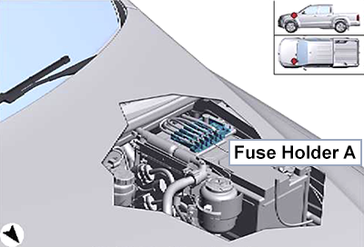
Diagram
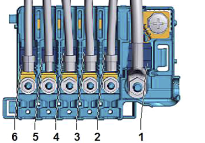
High Voltage Fuses
Assignment of the high voltage fuses in the engine compartment fuse box A
| No. | Amps | Description |
|---|---|---|
| 1 | 250A | Alternator |
| 2 | 125A | Automatic glow period control unit (3.0L engine), Current supply relay (Fresh air blower fuse 1, Fuse panel C: fuses 36, 43, 45, 47), Terminal 15 voltage supply relay (Fuse panel C: fuses 38-42, 49-51) |
| 3 | 125A | Fresh air blower fuse 1, Fuse panel C (fuses 53-68), Fuse panel F (fuses 5-12) |
| 4 | 100A | Radiator fan, Radiator fan control unit |
| 5 | 100A | Automatic glow period control unit (2.0L engine), Driver seat adjustment thermal fuse 1, Front passenger seat adjustment thermal fuse 1, ABS control unit fuse 1, Main relay (Engine control unit fuse, Fuse panel C: fuses 23-25, 32-34) |
| 6 | 125A | Fuse panel C (fuses 2-17) |
Passenger Compartment
Fuse Box (C)
Location
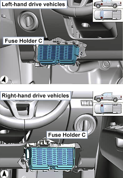
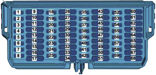
Diagram
Fuses
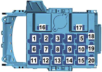
Assignment of the fuses in the passenger compartment fuse box C
| No. | Amps | Description |
|---|---|---|
| 1 | 10A | Washer pump |
| 2 | 5A / 7.5A | Onboard supply control unit (internal supply) (5A up to Dec 2017, 7.5A from Jan 2018) |
| 3 | 5A / 7.5A | Ignition/starter switch (5A up to Dec 2017, 7.5A from Jan 2018) |
| 4 | 5A / 7.5A | Steering column combination switch (headlight dipper and flasher switch) (5A up to Dec 2017, 7.5A from Jan 2018) |
| 5 | 15A | Automatic gearbox control unit |
| 6 | 5A / 7.5A | Battery monitor control unit, Onboard supply control unit (reference voltage) (5A up to Dec 2017, 7.5A from Jan 2018) |
| 7 | 15A | Onboard supply control unit (Interior monitoring switch, Front/Centre interior light, Front/Rear left/right entry lights, Left/Right side lights) |
| 8 | 15A | up to Dec 2017: Trailer detector control unit |
| 10A | from Jan 2018: Ignition/starter switch | |
| 9 | 30A | Starter motor relay, Starter, Starter relays 1 & 2 |
| 10 – 11 | 20A | Trailer detector control unit |
| 12 | 30A | Headlight main beam relay (Left/Right additional main beam bulbs, Centre left/right additional main beam bulbs) |
| 13 | 15A | up to Dec 2017: Ignition/starter switch |
| 20A | from Jan 2018: Trailer detector control unit | |
| 14 | 30A | ABS control unit |
| 15 | 5A / 7.5A | Coolant pump relay (Continued coolant circulation pump) (5A up to Dec 2017, 7.5A from Jan 2018) |
| 20A | Auxiliary heater control unit | |
| 16 | 20A | Onboard supply control unit (Signal bulb, Brake light bulb) |
| 17 | 20A | Onboard supply control unit (Left/Right fog light bulbs, Fuse 30 on fuse holder C) |
| 18 | 5A / 7.5A | Starter motor relay, Onboard supply control unit, Engine/motor control unit, Interface for external use (5A up to Dec 2017, 7.5A from Jan 2018) |
| 19 | 15A | Windscreen wiper switch, Washer pump switch (automatic wash/wipe and headlight washer system), Washer pump |
| 20 | 5A / 7.5A | Light switch, Brake light switch, Starter relays 1 & 2 (5A up to Dec 2017, 7.5A from Jan 2018) |
| 21 | 10A | Power steering control unit |
| 22 | 5A / 7.5A | Interface for external use (5A up to Dec 2017, 7.5A from Jan 2018) |
| 23 | 10A | Lambda probe 1 before catalytic converter, Lambda probe, Lambda probe heater |
| 15A | Lambda probe, Lambda probe heater, Lambda probe after catalytic converter, Lambda probe 1 heater after catalytic converter | |
| 24 | 10A | Fuel pressure regulating valve, Fuel metering valve |
| 10A | Oil level and oil temperature sender, Map-controlled engine cooling system thermostat, Exhaust gas recirculation cooler changeover valve, Exhaust gas recirculation cooling bypass valve 2, Coolant valve for cylinder head | |
| 10A | Charge pressure control solenoid valve, Activated charcoal filter solenoid valve 1, Camshaft control valve 1, Turbocharger air recirculation valve, Intake manifold flap valve | |
| 25 | 5A / 7.5A | Continued coolant circulation pump (5A up to Dec 2017, 7.5A from Jan 2018) |
| 10A | Fuel pressure regulating valve, Fuel metering valve | |
| 15A | up to Jul 2018: Engine/motor control unit | |
| 26 | 15A / 10A | Interface for external use (15A up to Dec 2017, 10A from Jan 2018) |
| 27 | 7.5A | Air mass meter, Charge pressure control solenoid valve, Exhaust gas recirculation cooler changeover valve |
| 7.5A | Air mass meter, Charge pressure control solenoid valve, Exhaust flap valve, Exhaust gas recirculation cooler changeover valve | |
| 7.5A | Air mass meter, Control unit 1 for particulate sensor (Control unit for sensor electronics, Particulate sensor), Relay for reducing agent metering system | |
| 28 | 5A / 7.5A | Clutch pedal switch, Fuel pump relay, Automatic glow period control unit (5A up to Dec 2017, 7.5A from Jan 2018) |
| 29 | 5A / 7.5A | Engine/motor control unit, Onboard supply control unit (5A up to Dec 2017, 7.5A from Jan 2018) |
| 30 | 5A / 7.5A | Interface for external use (5A up to Dec 2017, 7.5A from Jan 2018) |
| 31 | 5A / 7.5A | Coolant pump relay (up to Jul 2018), Auxiliary engine coolant pump relay, Auxiliary pump for heating (from Aug 2018), Radiator fan, Radiator fan control unit (5A up to Dec 2017, 7.5A from Jan 2018) |
| 32 | 30A | Fuse 27, 28, and 31 on fuse holder C |
| 33 | 15A | Ignition coils 1-4 with output stage |
| 20A | Engine/motor control unit | |
| 34 | 15A | Control unit for NOx sender 1 & 2, NOx senders 1 & 2 |
| 20A | Fuel pump control unit, Fuel system pressurisation pump | |
| 35 | – | Not used |
| 36 | 5A / 7.5A | Mirror adjustment switch (5A up to Dec 2017, 7.5A from Jan 2018) |
| 37 | 5A / 7.5A | Interface for external use (5A up to Dec 2017, 7.5A from Jan 2018) |
| 38 | 5A / 7.5A | Automatic gearbox control unit, Selector lever sensors control unit, Engine/motor control unit, Dash panel insert (5A up to Dec 2017, 7.5A from Jan 2018) |
| 39 | 10A | Airbag control unit, Warning lamp for airbag deactivated on front passenger side |
| 40 | 5A / 7.5A | Heater/heat output switch, TCS and ESP button, Driving program button, ABS control unit (up to Feb 2020), Alarm system relay 1, Steering column combination switch (Steering angle sender) (5A up to Dec 2017, 7.5A from Jan 2018) |
| 41 | 10A | Headlight range control regulator, Trailer detector control unit, Heater element for crankcase breather, Left/Right headlight range control motors, Automatic anti-dazzle interior mirror, Left/Right washer jet heater elements |
| 42 | 5A / 7.5A | ABS control unit, High-pressure sender, Air mass meter (up to Jul 2018), Oil level and oil temperature sender, Transfer box control unit, Normal operation warning lamp in transfer box operating unit, Diagnostic connection, Steering column combination switch (Cruise control system switch) (5A up to Dec 2017, 7.5A from Jan 2018) |
| 43 | 5A / 7.5A | Button for left/right seat heating (5A up to Dec 2017, 7.5A from Jan 2018) |
| 44 | 5A / 7.5A | Interface for external use (5A up to Dec 2017, 7.5A from Jan 2018) |
| 45 | 25A | Seat heating control unit |
| 46 | 5A / 7.5A | Interface for external use (5A up to Dec 2017, 7.5A from Jan 2018) |
| 47 | 15A | Interface for external use |
| 48 | 5A / 7.5A | Interface for external use (5A up to Dec 2017, 7.5A from Jan 2018) |
| 49 | 30A | Fuse 19 to 22 on fuse holder C |
| 50 | 10A | Start/Stop operation button, Reversing light switch, Tachograph, Differential lock control unit, Parking aid control unit, Load area illumination bulb, Steering column combination switch (Coil connector, Multifunction steering wheel control unit) |
| 51 | 5A / 7.5A | Steering column combination switch (Headlight dipper and flasher switch) (5A up to Dec 2017, 7.5A from Jan 2018) |
| 52 | 5A / 7.5A | Interface for external use (5A up to Dec 2017, 7.5A from Jan 2018) |
| 53 | 15A | Heater/heat output switch |
| 15A | Air conditioning system control unit | |
| 15A | Fresh air blower control unit, Climatronic control unit | |
| 54 | 10A | Tachograph, Selector lever sensors control unit, Ignition key withdrawal lock solenoid, Steering column combination switch (Steering angle sender) |
| 55 | 15A | Onboard supply control unit (Suppression filter, Heated exterior mirrors on driver/passenger side) |
| 56 | 10A | Relay for reducing agent metering system, Delivery unit for reducing agent metering system, Reducing agent tank |
| 57 | 5A / 7.5A | Engine/motor control unit (5A up to Dec 2017, 7.5A from Jan 2018) |
| 10A | ||
| 58 | 5A / 7.5A | Light switch, Main relay, Emergency call module control unit, Dash panel insert (5A up to Dec 2017, 7.5A from Jan 2018) |
| 59 | 10A | Rain and light sensor (from Aug 2018), Anti-theft alarm sensor (from Aug 2018), Alarm horn, Electric fuel pump 2 relay, Tyre Pressure Monitoring System control unit, Roof electronics control unit (up to Dec 2017), Roof display unit, Load area illumination bulb, Remote control receiver for auxiliary coolant heater, Reversing camera, Diagnostic connection, Auxiliary coolant heater relay, Auxiliary engine coolant pump relay (Circulation pump) |
| 60 | 25A | Control unit 1 for information electronics, Radio |
| 61 | 40A | Interface for external use |
| 62 | 30A | Onboard supply control unit (Heated rear window, Heated rear window relay) |
| 63 | 30A | Onboard supply control unit (Treble horn, Bass horn, Alarm system horn, Alarm system relay 1, Interface for external use) |
| 64 | 30A | LHD Vehicles: Driver door control unit, Rear left door control unit |
| 30A | RHD Vehicles: Driver door control unit, Rear right door control unit | |
| 65 | 30A | LHD Vehicles: Front passenger door control unit, Rear right door control unit, Onboard supply control unit (Fuel tank filler flap central locking actuator, Central locking lock units) |
| 30A | RHD Vehicles: Front passenger door control unit, Rear left door control unit, Onboard supply control unit (Fuel tank filler flap central locking actuator, Central locking lock units) | |
| 66 | 20A | Onboard supply control unit (Rear left/right fog light bulbs, Front left/right headlights, Left/right reversing light bulbs) |
| 67 | 20A | Onboard supply control unit (Front left/right headlights, Left/right daytime running light bulbs) |
| 68 | 30A | Onboard supply control unit (Wiper motor control unit, Windscreen wiper motor) |
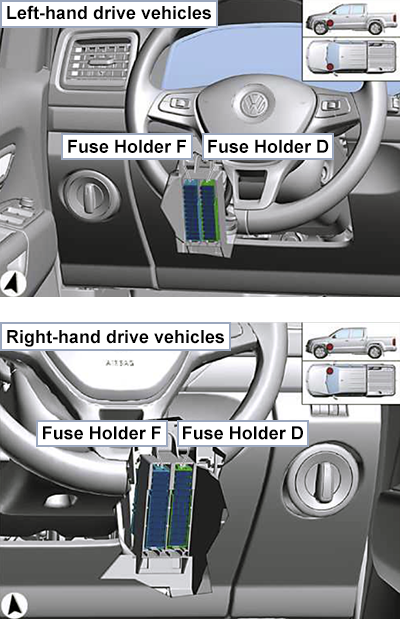
Fuse Box (D, F)
Location
Diagram
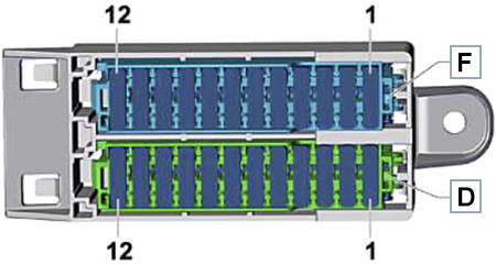
Fuses
Assignment of the fuses in the passenger compartment fuse box D and F
| No. | Amps | Description |
|---|---|---|
| 1 | – | not assigned |
| 2 | – | not assigned |
| 3 | – | not assigned |
| 4 | – | not assigned |
| 5 | 20A | Electric socket -U- Cigarette lighter -U1- |
| 6 | 30A | Transfer box control unit -J646- |
| 7 | 15A | Differential lock control unit -J187- |
| 8 | 30A | Heated rear window relay -J9- – Heated rear window for hardtop -Z129- |
| 9 | 30A | Control unit for reducing agent heater -J891 – |
| 10 | 30A | Fuel pump relay -J17- – Fuel pressure regulating valve -N276- |
| 30A | Fuel pump relay -J17- Electric fuel pump 2 relay -J49- – Fuel delivery unit -GX1- | |
| 11 | 20A | 12 V socket 4 -U20- |
| 12 | 20A | 12 V socket 2 -U18- 12 V socket 3 -U19- |
Relays (1)
Location
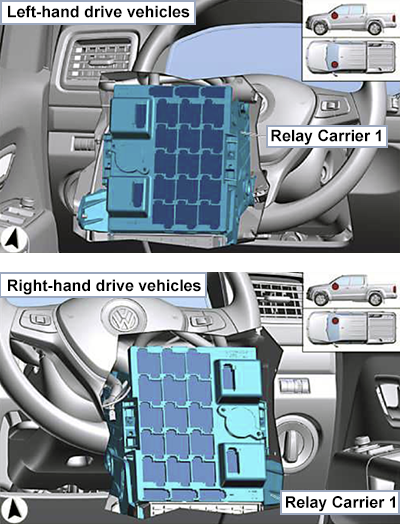
Diagram
Relays
Assignment of the relays in the passenger compartment relay carrier 1
| No. | Description |
|---|---|
| 1 – 5 | Not used |
| 6 | LHD Vehicles: Engine control unit fuse |
| 7 | RHD Vehicles: Engine control unit fuse |
| 8 | Starter motor relay, Starter relays 1 & 2 |
| 9 | Diesel: Additional coolant pump relay General: Auxiliary coolant heater relay |
| 10 | Headlight main beam relay, Alarm system relay 1 |
| 11 | LHD Vehicles: Terminal 15 voltage supply relay, Fresh air blower fuse 1, ABS control unit fuse 1 |
| 12 | LHD Vehicles: Fuel pump relay RHD Vehicles: Terminal 15 voltage supply relay |
| 13 | Current supply relay |
| 14 | Not used |
| 15 | Diesel: Electric fuel pump 2 relay Petrol: Coolant pump relay |
| 16 – 18 | Not used |
| 19 | RHD Vehicles: Fresh air blower fuse 1, ABS control unit fuse 1 |
| 20 | RHD Vehicles: Fuel pump relay |
Relays (2)
Location
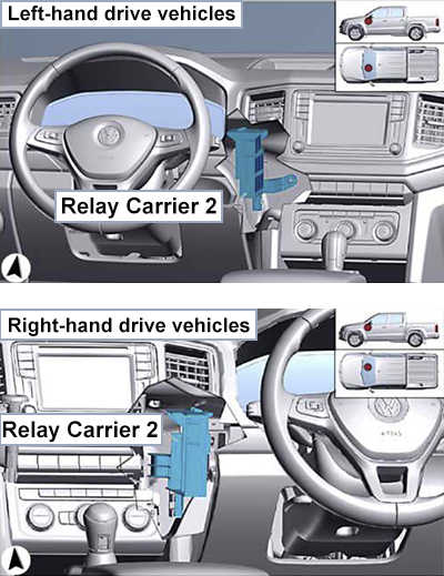
Diagram (LHD)
Left-hand drive vehicles.
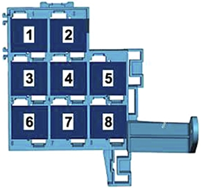
Relays
Assignment of the relays in the passenger compartment relay carrier 2 (Left-Hand Drive vehicles)
Diagram (RHD)
Right-hand drive vehicles.
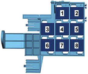
Relays
Assignment of the relays in the passenger compartment relay carrier 2 (Right-Hand Drive vehicles)