")
")

Looking for Volkswagen Caddy fuse box diagrams? This article covers the facelifted third-generation Volkswagen Caddy (Model Code: 2K), produced from 2011, and includes fuse box diagrams for Volkswagen Caddy 2011, 2012, 2013, 2014, 2015, 2016, 2017, 2018, 2019 and 2020, along with details about the location of the fuse panels inside the vehicle and a clear explanation of the assignment of each fuse (fuse layout).
What’s Included
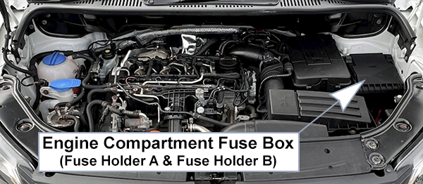
ToggleFuse Box (A, B)
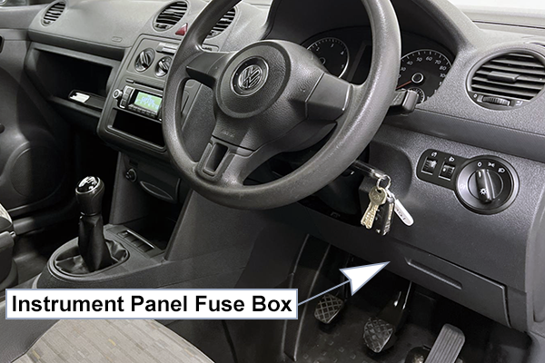
Fuse Box Location
Fuse Box Diagram (A)
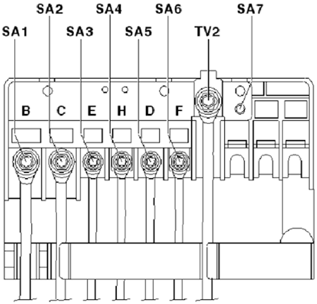
High Voltage Fuses
Assignment of the high voltage fuses in the engine compartment (Fuse Box A)
| No. | Amps | Description |
|---|---|---|
| SA1 | 150A | Alternator -C- |
| 200A | Alternator -C- (models with 140A generator) | |
| SA2 | 80A | Power steering control unit -J500- Electromechanical power steering motor-V187- |
| SA3 | 50A | Radiator fan control unit -J293- |
| SA4 | 80A | X-contact relief relay -J59- – Fuse holder C (Instrument Panel) -SC28- up to -SC33- |
| SA5 | 80A | Fuse holder C -SC- (Instrument Panel) -SC20- up to -SC24- and -SC43- up to -SC53- |
| SA6 | 40A | Low heat output relay -J359- |
| SA7 | 80A | High heat output relay -J360- |
| TV2 | Battery Terminal | Fuse box A (SA), Fuse box B (SB) |
Fuse Box Diagram (B)
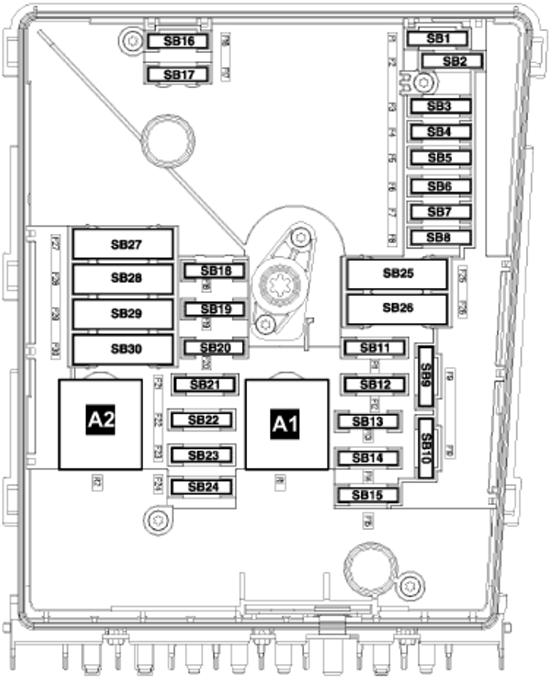
Fuses
Assignment of the fuses in the engine compartment (Fuse Box B)
| No. | Amps | Description |
|---|---|---|
| 1 | – | Not used |
| 2 | 30A | Mechatronic unit for dual clutch gearbox |
| 3 | 5A | Battery monitoring control unit, Onboard supply control unit |
| 4 | 20A | ABS control unit, ABS hydraulic unit |
| 5 | 15A | Mechatronic unit for dual clutch gearbox |
| 6 | 5A | Control unit in dash panel insert, Steering column electronics control unit |
| 7 | 40A | Terminal 15 voltage supply relay (Fuse holder C: SC9 to SC16, SC25 to SC27) |
| 8 | 15A | Control unit with display for radio and navigation, Radio, Voltage stabiliser (with start/stop system: fuses SC57 & SC58) |
| 9 | 5A | Mobile telephone operating electronics control unit (without start/stop system) |
| 10 | 5A | Main relay, Engine control unit, Engine component current supply relay |
| 11 | 30A | Auxiliary heater control unit |
| 12 | 5A | Data bus diagnostic interface |
| 13 | 15A (petrol) 30A (diesel) | Engine control unit |
| 14 | 15A / 20A | 15A: Fuel pressure regulating valve (diesel), Fuel metering valve (diesel) 20A: Ignition transformer, Ignition coils 1-4 with output stage |
| 15 | 5A / 10A / 15A | 5A: Low/High heat output relays (diesel), Fuel pump relay, Electric fuel pump 2 relay, Automatic glow period control unit 10A: Lambda probe heaters, Low/High heat output relays, Fuel pump switch-off relay (engine code BSX), Gas injection valves 1-4 (engine code BSX) 15A: High-pressure valve for gas mode (engine code CHGA), Valve for gas tank (engine code CHGA), Sensor for gas level gauge (engine code CHGA), Gas injection valves 1-4 (engine code CHGA) |
| 16 | 30A | Onboard supply control unit (Right foglamp, Right cornering light, Rear fog lights, Right daytime running light, Left side light, Right tail light, Rear left/Front right turn signals, Left brake light, Right reversing light, Left turn signal repeater, High-mounted brake light, Right headlight dipped/main beam) |
| 17 | 15A | Horn relay |
| 18 | 30A | Special vehicle control unit |
| 19 | 30A | Wiper motor control unit |
| 20 | 10A | Fuel tank shut-off valves 1-5 (engine code BSX), Coolant circulation pump |
| 21 | 10A / 15A | 10A: Lambda probe heater (diesel) 15A: Fuel pump control unit, Lambda probe heaters |
| 22 | 5A | Clutch position sender, Brake light switch (from Nov 2011) |
| 23 | 5A / 10A / 15A | 5A: Additional coolant pump relay 10A: Air mass meter (diesel), Charge pressure control solenoid valve (diesel), Exhaust gas recirculation cooler changeover valve (diesel), Control unit for gas mode, Relay for gas shut-off valves (engine code BSX), High-pressure valve for gas mode (engine code BSX) 15A: Fuel pressure regulating valve |
| 24 | 10A | Radiator fan control unit, Secondary air pump relay, Additional coolant pump relay, Activated charcoal filter solenoid valve 1, Coolant regulating valve, Variable intake manifold changeover valve, Coolant circulation pump 2, Injectors 1-4 (engine code BSX) |
| 25 | 40A | ABS hydraulic pump, ABS control unit |
| 26 | 30A | Onboard supply control unit (Left cornering light, Left fog light, Rear fog lights, Left daytime running light, Right side light, Left tail light, Front left/Rear right turn signals, Right brake light, Left reversing light, Right turn signal repeater, Left headlight dipped/main beam) |
| 27 | 40A / 50A | 40A: Secondary air pump motor 50A: Automatic glow period control unit |
| 28 | – | Not used |
| 29 | 30A / 50A | 30A: Fuses 18 and 19 on fuse holder C 50A: Fuses 35, 39, 54, 55, 59, 60 on fuse holder C |
| 30 | 50A | Fuse holder C (fuses SC40 to SC42) |
Relays
Assignment of the relays in the engine compartment (Fuse Box B)
Fuse Box (C)
Fuse Box Location
Left-hand drive vehicles: Under the headlight switch.
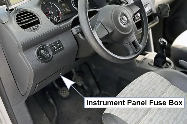
Right-hand drive vehicles: Under the headlight switch.
Fuse Box Diagram
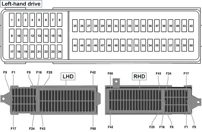
Fuses
Assignment of the fuses in the passenger compartment (Fuse Box C)
| No. | Amps | Description |
|---|---|---|
| F1 – F8 | – | Not used |
| F9 | 10A | Special vehicles: 4-pin connector Pin 1, 10-pin connector Pin 4 (Interface for special functions) |
| F10 | 5A | Fuel pump relay, Main relay, Gas mode control unit, Terminal 50 voltage supply relay, Starter relay 1, Voltage stabiliser, Data bus diagnostic interface, Engine control unit |
| F11 | 5A | Parking aid control unit, Park assist steering control unit |
| F12 | 5A / 10A / 20A | Special vehicles: 5A: Taximeter, Mirror taximeter 10A (up to Oct 2011): 2-pin connectors Pin 1, 28-pin connector Pin 13 20A (from Nov 2011): 8-pin connector Pin 8, 28-pin connectors Pin 20 |
| F13 | 7.5A | Brake light switch, Headlight range control regulator, TCS and ESP button, Tyre Pressure Loss Indicator button, Start/Stop operation button, ABS control unit, Trailer detector control unit, All-wheel drive control unit, Power steering control unit, Selector lever sensors control unit, Mechatronic unit for dual clutch gearbox, Left/Right headlight range control motors, Control unit for cornering light and headlight range control |
| F14 | 10A | Reversing light switch, Air mass meter, Auxiliary heater operation relay, Control unit in dash panel insert, Heater element for crankcase breather, Activated charcoal filter solenoid valve 1, Diagnostic connection, 16-pin connector Pin 1 |
| F15 | 5A | Airbag control unit, Warning lamp for airbag deactivated on front passenger side |
| F16 | 5A | Light switch, Heater/heat output switch, High-pressure sender, Air quality sensor, Oil level and oil temperature sender, Automatic anti-dazzle interior mirror |
| F17 | – | Not used |
| F18 | 10A | Special vehicles: Taxi alarm remote control (control unit), 10-pin connector Pin 6 (Interface for special functions) |
| F19 | 10A | Special vehicles: Taximeter, Mirror taximeter, Taxi alarm remote control (control unit), Two-way radio, Printer, 10-pin connector Pin 7 (Interface for special functions) |
| F20 | 20A | Cigarette lighter |
| F21 | 10A | Light switch, Heater/heat output switch, Rain and light sensor, Heated rear window relay, Climatronic control unit, Air conditioning system control unit, Horn relay, Remote control receiver for auxiliary coolant heater, Selector lever sensors control unit, Diagnostic connection, 16-pin connector Pin 16, Interior illumination switch (camper), Rear interior light (camper) |
| F22 | 10A | from May 2011: Onboard supply control unit |
| F23 | 5A / 10A | Special vehicles: 5A: Interior light switch (taxi), Taxi sign switch, 10-pin connector Pin 1 (Interface for special functions) 10A (up to Oct 2011): 3-pin connector Pin 1, Flashing lights relay |
| F24 | 5A | Interior monitoring sensor, Vehicle inclination sender, Anti-theft alarm sensor, Alarm horn, Onboard supply control unit |
| F25 | 10A | Output module for left headlight |
| F26 | 10A | Output module for right headlight |
| F27 | – | Not used |
| F28 | 20A | 12 V socket 3 (in storage compartment) |
| F29 | 15A | Rear window wiper motor |
| F30 | – | Not used |
| F31 | 5A | Heater/heat output switch, Left/Right washer jet heater elements |
| F32 | – | Not used |
| F33 | 40A | Air conditioning system control unit, Heater/heat output switch |
| F34 | – | Not used |
| F35 | 10A | Special vehicles (up to Oct 2011): Fluorescent light in rear/centre of high roof |
| F36 – F38 | – | Not used |
| F39 | 20A / 30A | Special vehicles: 20A (up to Oct 2011): 10-pin connector Pin 1 30A (from Nov 2011): 4-pin connector Pin 1 |
| F40 – F42 | 20A | Trailer detector control unit |
| F43 | 15A | Fuel pump relay, Electric fuel pump 2 relay (Supplementary fuel pump) |
| F44 | 40A | Fresh air blower control unit (Fresh air blower) |
| F45 | 20A | Headlight washer system relay (Headlight washer system pump) |
| F46 | 10A / 30A | 10A: Onboard supply control unit (up to Apr 2011: Front interior light, Luggage compartment light, Glove compartment light, Rear interior light), Driver door control unit (from May 2011: convenience system without electric window regulators, LHD), Front passenger door control unit (from May 2011: convenience system without electric window regulators, RHD) 30A: Driver door control unit (from May 2011: convenience system with electric window regulators, LHD), Front passenger door control unit (from May 2011: convenience system with electric window regulators, RHD) |
| F47 | 30A | Cigarette lighter (up to Oct 2012), X-contact relief relay (from Nov 2012, models with Climatronic: Fuse holder C -SC28- to -SC33-) |
| F48 | 30A | Heated front seats control unit |
| F49 | 10A / 30A | 10A: Driver door control unit (up to Apr 2011: convenience system without electric window regulators, LHD), Driver door control unit (from May 2011: convenience system without electric window regulators, RHD), Front passenger door control unit (from May 2011: convenience system without electric window regulators, LHD) 30A: Driver door control unit (up to Apr 2011: convenience system with electric window regulators, LHD), Driver door control unit (from May 2011: convenience system with electric window regulators, RHD), Front passenger door control unit (from May 2011: convenience system with electric window regulators, LHD) |
| F50 | 20A | Onboard supply control unit (Rear window wiper motor, Windscreen and rear window washer pump, Washer pump) |
| F51 | 15A / 30A | 15A: Trailer voltage supply relay (Trailer socket) 30A: Special vehicles: 10-pin connector Pins 4 & 5 |
| F52 | 25A | Heated rear window relay (Heated rear window, Heated rear windows in left/right wing doors), Fresh air blower relay (Fresh air blower series resistor with overheating fuse, Fresh air blower) |
| F53 | 15A (up to Oct 2012) 20A (from Nov 2012) | 12 V socket (rear centre console), 12 V socket 2 (rear left side panel) |
| F54 | 15A | Special vehicles (from Nov 2011): Switch-over relay 1 for roof ventilator |
| F55 | 15A | Special vehicles (from Nov 2011): 8-pin connector Pins 4 |
| F56 | – | Not used |
| F57 | 5A | Control unit in dash panel insert (with start/stop system), Steering column electronics control unit (with start/stop system) |
| F58 | 5A | Mobile telephone operating electronics control unit (with start/stop system) |
| F59 | 5A | Special vehicles: 2-way radio switch, Ignition bypass button, Button for daytime running light switch-off, Accident data memory |
| F60 | 30A | Special vehicles: 3-pin connector Pin 1 |
Relay Box
Location and Diagram
The relay box is located in the dashboard in the same area as Fuse Box C, positioned above it.
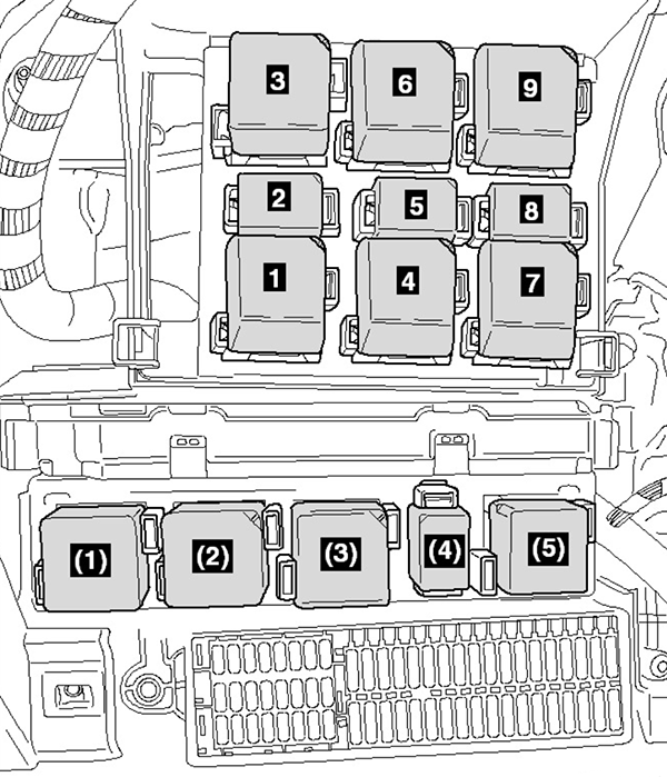
Relays
Assignment of the relays in the passenger compartment
| No. | Description |
|---|---|
| 1.1 | Horn relay (646) |
| 1.2 | Headlight washer system relay (646) |
| 2 | Fuel pump relay (646) |
| 3 | Terminal 50 voltage supply relay (645), Starter relay 1 (645) (from Nov 2011) |
| 4 | up to Oct 2011: Auxiliary heater operation relay (645) Nov 2011 to Apr 2012: X-contact relief relay (644) from May 2012: Heated rear window relay (645) |
| 5 | Fuel supply relay (646) |
| 6 | up to Oct 2011: Not assigned from Nov 2011: Starter relay 2 (507) |
| 7 | up to Oct 2011: High heat output relay (644) from Nov 2011: Terminal 15 voltage supply relay (645) |
| 8 | Electric fuel pump 2 relay (646), Fuel pump switch-off relay (646) |
| 9 | up to Oct 2011: Low heat output relay (645) Nov 2011 to Apr 2012: Heated rear window relay (645) from May 2012: X-contact relief relay (644, without Climatronic / 645 with Climatronic after Nov 2012) |
| (1) | up to Oct 2011: X-contact relief relay (644) from Nov 2011: Auxiliary heater operation relay (645) |
| (2) | up to Oct 2011: Terminal 15 voltage supply relay (645) from Nov 2011: High heat output relay (644) |
| (3) | up to Oct 2011: Heated rear window relay (645) from Nov 2011: Low heat output relay (645) |
| (4) | Fresh air blower relay (646), Trailer voltage supply relay (646, RHD vehicles from May 2012) |
| (5) | up to Oct 2011: Starter relay 2 (507) from Nov 2011: Flashing lights relay (645), Trailer voltage supply relay (646, LHD vehicles from May 2012) |
Additional Relay
Location and Diagram
An additional relay is located in the driver-side footwell.
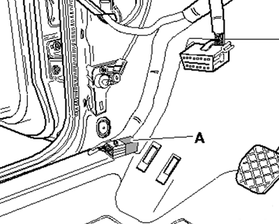
Relay
Assignment of the additional relay in the footwell