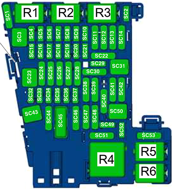
| SC1 – SC3 | – | – |
| SC4 | 10A
7.5A | up to Jun 2018: Vehicle electrical system control module – Anti-theft alarm system (10A)
from Jul 2018: Alarm horn (7.5A / 10A for North America) |
| SC5 | 5A
7.5A | up to Jun 2018: Data bus on board diagnostic interface (5A)
from Jul 2018: Data bus on board diagnostic interface (7.5A) |
| SC6 | 5A | up to Oct 2015: Anti-theft alarm system sensor
from Nov 2015: Selector lever |
| SC7 | 10A | Heater and A/C controls, Climatronic control module, Rear window defogger relay, Selector lever (up to Oct 2015) |
| SC8 | 10A
7.5A | up to Jun 2018: Rotary light switch, Electromechanical parking brake button, Rain/light recognition sensor, Diagnostic connection, Anti-theft alarm system sensor (from Nov 2015) (10A)
from Jul 2018: Same components (7.5A) |
| SC9 | 1A
5A
7.5A | Steering column electronics control module (1A up to Oct 2015, 5A Nov 2015 to Jun 2018, 7.5A from Jul 2018) |
| SC10 | 10A
7.5A | up to Oct 2015: Front information display control head (10A)
from Nov 2015: Front information display control head (7.5A) |
| SC11 | 25A
40A | up to Apr 2017: Left front seat belt tensioner control module (25A)
from May 2017: Vehicle electrical system control module – Left front headlamp (40A) |
| SC12 | 20A | Information electronics control module 1 |
| SC13 | 10A
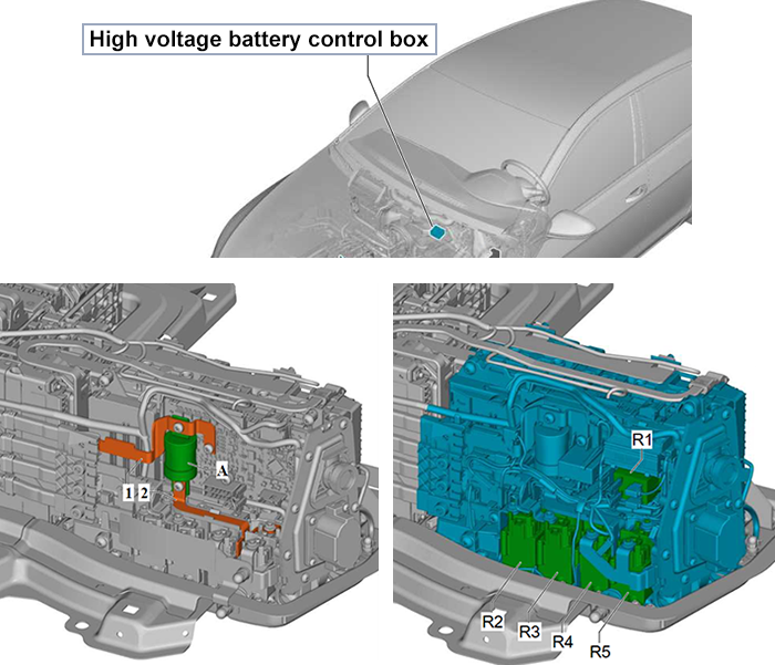
25A | up to Apr 2017: High-voltage battery 1, High-voltage system maintenance connector (10A)
from May 2017: Left front seat belt tensioner control module (25A) |
| SC14 | 30A
40A | up to Apr 2016: Fresh air blower control module (30A)
from May 2016: Fresh air blower control module (40A) |
| SC15 | 10A | Electronic steering column lock control module |
| SC16 | 7.5A | Mobile communication 2-way signal amplifier, Telephone baseplate, USB distributor, Chip card reader control module, TV tuner, Voltage converter for USB charge module (up to Apr 2017) |
| SC17 | 5A
7.5A | Instrument cluster, Control module for emergency call module and communication unit (5A up to Jun 2018, 7.5A from Jul 2018), Telematics Control Module for Real-Time Monitoring (from Jul 2019) |
| SC18 | 7.5A | Rearview camera, Release button in rear lid handle |
| SC19 | 7.5A | Access/start system interface |
| SC20 | 5A
7.5A | up to Jun 2019: High-voltage battery charging voltage control module (5A)
from Jul 2019: High-voltage battery charging voltage control module (7.5A) |
| SC21 – SC22 | – | – |
| SC23 | 40A
– | up to Apr 2017: Vehicle electrical system control module – Right front headlamp
from May 2017: Not Assigned |
| SC24 | –
40A | up to Apr 2017: Not Assigned
from May 2017: Vehicle electrical system control module – Right front headlamp |
| SC25 | 30A | Driver and Front Passenger Door Control Modules, Left and Right Rear Window Regulator Motors |
| SC26 | 30A | Vehicle electrical system control module – Front heated seat |
| SC27 | 30A | up to Apr 2017: Digital sound system control module
from May 2017: Vehicle electrical system control module – Terminal 30 |
| SC28 – SC29 | – | – |
| SC30 | –
10A | up to Apr 2017: Not Assigned
from May 2017: High-voltage battery 1, High-voltage system maintenance connector |
| SC31 | 40A
– | up to Apr 2017: Vehicle electrical system control module – Left front headlamp
from May 2017: Not Assigned |
| SC32 | 7.5A / 10A | Driver assistance systems front camera, Distance regulation control module, Parking Aid Control Module, Parallel Parking Assistance Control Module, Blind spot detection control modules 1 and 2 |
| SC33 | 5A
7.5A | up to Jun 2018: Airbag control module, Front passenger airbag disabled indicator lamp (5A)
from Jul 2018: Same components (7.5A) |
| SC34 | 7.5A | Rotary light switch, Interior rearview mirror, Sockets relay, Air quality sensor, Electromechanical parking brake button |
| SC35 | 10A
7.5A | up to Jun 2018: Diagnostic connection, Headlamp Range Control and Instrument Illumination Regulator, Cornering lamp and headlamp range control module (10A)
from Jul 2018: Same components (7.5A) |
| SC36 | 5A
10A / 7.5A | up to Apr 2017: Right LED headlamp power output module 1 (5A)
from May 2017: Right front headlamp, Right LED headlamp power output module 1, Right Headlamp Power Output Module, Left Light Control Module (10A / 7.5A for LED headlamps) |
| SC37 | 5A
10A / 7.5A | up to Apr 2017: Left LED headlamp power output module 1 (5A)
from May 2017: Left front headlamp, Left LED headlamp power output module 1, Left Headlamp Power Output Module, Right Light Control Module (10A / 7.5A for LED headlamps) |
| SC38 | – | – |
| SC39 | 30A | Driver and Front Passenger Door Control Modules, Left and Right Rear Window Regulator Motors |
| SC40 | 20A | Cigarette Lighter, 12 V socket, 12 V socket 2
*Note: Factory supplied by terminal 15, can be swapped to terminal 30. Ensure equipment is disconnected when engine is off to prevent battery drain. |
| SC41 | 25A | Right front seat belt tensioner control module |
| SC42 | 40A | Vehicle electrical system control module – Central locking system |
| SC43 | 30A | up to Apr 2017: Vehicle electrical system control module – Terminal 30
from May 2017: Digital sound system control module |
| SC44 | – | – |
| SC45 | 15A | Left Front Seat Adjustment Control Head |
| SC46 | – | – |
| SC47 | 15A | Rear window wiper motor |
| SC48 | 7.5A | Engine sound generator control module |
| SC49 | 5A
7.5A | up to Apr 2017: High-voltage battery charging voltage control module (5A)
from May 2017: Clutch position sensor, Starter relays 1 & 2 (7.5A) |
| SC50 – SC52 | – | – |
| SC53 | 30A | Rear window defogger relay |