
Looking for Volkswagen Up fuse box diagrams? This article covers the city car Volkswagen Up, available from 2011 to 2023, and includes fuse box diagrams for Volkswagen Up 2011, 2012, 2013, 2014, 2015, 2016, 2017, 2018, 2019, 2020, 2021, 2022 and 2023, along with information about the location of the fuse panels inside the car and the assignment of each fuse (fuse layout), making it easier to understand and troubleshoot the vehicle’s electrical system.
What’s Included
ToggleEngine Compartment
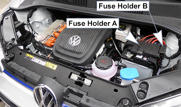
Fuse Box Location
The fuses are located underneath a cover on the vehicle battery.
Fuse Box Diagram
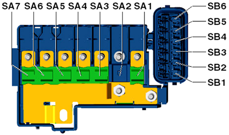
The fuse strip (multi-fuse) must be replaced as a complete unit. List of fuses in the front compartment (From July 2013)
Fuse Box (A)
Assignment of the fuses in the engine compartment fuse holder A
Fuse Box (B)
Assignment of the fuses in the engine compartment fuse holder B
Passenger Compartment
Fuse Box Location (C)
The fuses are located underneath the steering wheel on the underside of the dash panel.
- Push the locking lever (1) until the cover can be opened.
- Fold the cover down.
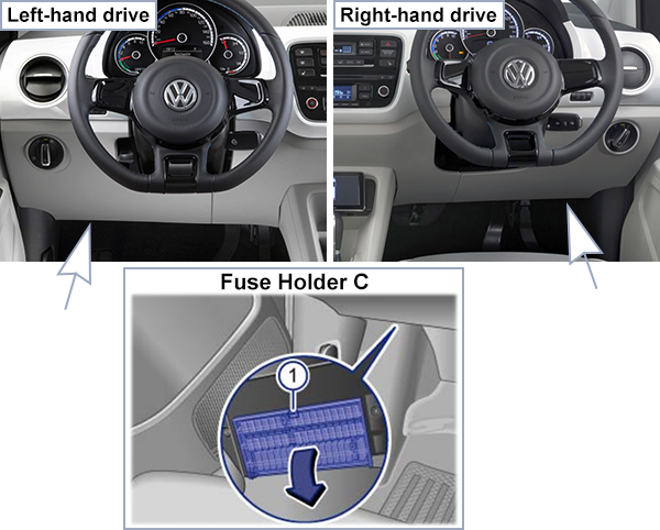
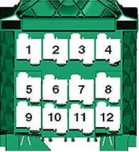
Fuse Box Diagrams (C)
From July 2013
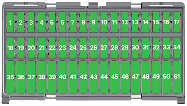
Assignment of fuses in the Fuse Holder C (From July 2013)
| No. | Amps | Description |
|---|---|---|
| 1 | 7.5A | Dash panel insert Engine/motor control unit |
| 2 | 7.5A | High-voltage battery 1 Diagnostic connection |
| 3 | – | – |
| 4 | – | – |
| 5 | 7.5A | Steering column electronics control unit Onboard supply control unit |
| 6 | 7.5A | Mirror adjustment switch Headlight range control regulator Left headlight range control motor Right headlight range control motor |
| 7 | 10A | Power and control electronics for electric drive |
| 8 | 7.5A | Selector lever Brake servo control unit Charge voltage control unit for high-voltage battery Power and control electronics for electric drive |
| 9 | 7.5A | Centre switch module 2 in dash panel Airbag control unit |
| 10 | 7.5A | Parking aid control unit |
| 11 | – | – |
| 12 | 7.5A | Light switch |
| 13 | – | – |
| 14 | 15A | Rear window wiper motor |
| 15 | 15A | Light switch |
| 16 | 7.5A | Terminal 15 voltage supply relay Power steering control unit |
| 17 | 15A | Steering column electronics control unit |
| 18 | 15A | Charging unit 1 for high-voltage battery |
| 19 | – | – |
| 20 | 7.5A | ABS control unit Emergency braking function sensor unit |
| 21 | – | – |
| 22 | – | – |
| 23 | 7.5A | Engine/motor control unit |
| 24 | 15A | Steering column electronics control unit – Headlight flasher switch |
| 25 | 10A | Windscreen and rear window washer pump |
| 26 | 7.5A | Main relay Dash panel insert |
| 27 | 7.5A | Onboard supply control unit – Front interior light – Front passenger reading light – Driver side reading light |
| 28 | 7.5A | Diagnostic connection |
| 29 | 7.5A | Onboard supply control unit |
| 30 | 7.5A | Onboard supply control unit – Heated exterior mirror on driver side – Heated exterior mirror on passenger side |
| 31 | 10A | Radiator fan |
| 32 | 15A | Onboard supply control unit – Turn signal/brake light |
| 33 | 10A | Front right headlight – Right headlight main beam bulb |
| 34 | 10A | Dash panel insert Onboard supply control unit Front left headlight – Left headlight main beam bulb |
| 35 | – | – |
| 36 | 30A | Cigarette lighter |
| 37 | – | – |
| 38 | 15A | Radio |
| 39 | 30A | Sliding sunroof adjustment control unit |
| 40 | 15A | Engine/motor control unit |
| 41 | 25A | Onboard supply control unit – Central locking |
| 42 | 20A | Coolant pump for high-temperature circuit Coolant circulation pump before power and control electronics for electric drive |
| 43 | 20A | Centre switch module in dash panel Centre switch module 2 in dash panel Heated front seats control unit |
| 44 | 15A | High-voltage battery 1 |
| 45 | 20A | Light switch |
| 46 | 30A | Onboard supply control unit – Heated rear window |
| 47 | 30A | Front right window regulator switch |
| 48 | 20A | Onboard supply control unit – Treble horn – Bass horn |
| 49 | 30A | Onboard supply control unit – Wiper motor control unit |
| 50 | 20A | Onboard supply control unit – Left tail light – Left reversing light bulb – Right tail light – Right reversing light bulb |
| 51 | 30A | Front left window regulator switch |
From May 2014
Assignment of fuses in the Fuse Holder C (From May 2014)
| No. | Amps | Description |
|---|---|---|
| 1 | 7.5A | Dash panel insert Engine/motor control unit |
| 2 | 7.5A | High-voltage battery 1 Diagnostic connection |
| 3 | – | – |
| 4 | – | – |
| 5 | 7.5A | Steering column electronics control unit Onboard supply control unit |
| 6 | 7.5A | Mirror adjustment switch Headlight range control regulator Left headlight range control motor Right headlight range control motor |
| 7 | 10A | Power and control electronics for electric drive |
| 8 | 7.5A | Selector lever Brake servo control unit Charge voltage control unit for high-voltage battery Power and control electronics for electric drive |
| 9 | 7.5A | Centre switch module 2 in dash panel Airbag control unit |
| 10 | 7.5A | Parking aid control unit |
| 11 | – | – |
| 12 | 7.5A | Light switch |
| 13 | – | – |
| 14 | 15A | Rear window wiper motor |
| 15 | 15A | Light switch -E1- |
| 16 | 7.5A | Terminal 15 voltage supply relay Power steering control unit |
| 17 | 15A | Steering column electronics control unit |
| 18 | 15A | Charging unit 1 for high-voltage battery |
| 19 | – | – |
| 20 | 7.5A | ABS control unit Emergency braking function sensor unit- |
| 21 | – | – |
| 22 | – | – |
| 23 | 7.5A | Engine/motor control unit |
| 24 | 15A | Steering column electronics control unit – Headlight flasher switch |
| 25 | 10A | Windscreen and rear window washer pump |
| 26 | 7.5A | Main relay Dash panel insert |
| 27 | 7.5A | Onboard supply control unit – Front interior light – Front passenger reading light – Driver side reading light |
| 28 | 10A | Diagnostic connection |
| 29 | 7.5A | Onboard supply control unit |
| 30 | 7.5A | Onboard supply control unit – Heated exterior mirror on driver side – Heated exterior mirror on passenger side |
| 31 | 10A | Radiator fan |
| 32 | 15A | Onboard supply control unit – Turn signal/brake light |
| 33 | 10A | Front right headlight – Right headlight main beam bulb |
| 34 | 10A | Dash panel insert Onboard supply control unit Front left headlight – Left headlight main beam bulb |
| 35 | – | – |
| 36 | 20A | Cigarette lighter |
| 37 | 15A | Engine sound generator control unit |
| 38 | 15A | Radio |
| 39 | 30A | Sliding sunroof adjustment control unit |
| 40 | 15A | Engine/motor control unit |
| 41 | 25A 20A * | Onboard supply control unit – Central locking |
| 42 | 20A | Coolant pump for high-temperature circui Coolant circulation pump before power and control electronics for electric drive |
| 43 | 20A | Centre switch module in dash panel Centre switch module 2 in dash panel Heated front seats control unit |
| 44 | 7.5A | High-voltage battery 1 |
| 45 | 20A | Light switch |
| 46 | 30A | Onboard supply control unit – Heated rear window |
| 47 | 30A | Front right window regulator switch |
| 48 | 20A | Onboard supply control unit – Treble horn – Bass horn |
| 49 | 30A | Onboard supply control unit – Wiper motor control unit |
| 50 | 20A | Onboard supply control unit – Left tail light – Left reversing light bulb – Right tail light – Right reversing light bulb |
| 51 | 30A | Front left window regulator switch |
| * Only right-hand drive models | ||
From August 2016
Assignment of fuses in the Fuse Holder C (From August 2016)
| No. | Amps | Description |
|---|---|---|
| 1 | 7.5A | Dash panel insert Engine/motor control unit |
| 2 | 7.5A | High-voltage battery 1 Diagnostic connection |
| 3 | 7.5A | Reversing camera |
| 4 | – | – |
| 5 | 7.5A | Steering column electronics control unit Onboard supply control unit |
| 6 | 7.5A | Mirror adjustment switch Headlight range control regulator Left headlight range control motor Right headlight range control motor |
| 7 | 10A | Power and control electronics for electric drive |
| 8 | 7.5A | Selector lever Brake servo control unit Charge voltage control unit for high-voltage battery Power and control electronics for electric drive |
| 9 | 7.5A | Centre switch module 2 in dash panel Airbag control unit |
| 10 | 7.5A | Parking aid control unit |
| 11 | 7.5A | **Daytime running light switch-on relay |
| 12 | – | – |
| 13 | – | – |
| 14 | 15A | Rear window wiper motor |
| 15 | 15A | Light switch |
| 16 | 7.5A | Terminal 15 voltage supply relay Power steering control unit |
| 17 | 15A | Steering column electronics control unit |
| 18 | 15A | Charging unit 1 for high-voltage battery |
| 19 | – | – |
| 20 | 7.5A | ABS control unit Emergency braking function sensor unit Steering column electronics control unit |
| 21 | – | – |
| 22 | – | – |
| 23 | 7.5A | Engine/motor control unit |
| 24 | 15A | Steering column electronics control unit – Headlight flasher switch |
| 25 | 10A | Windscreen and rear window washer pump |
| 26 | 7.5A | Main relay Dash panel insert |
| 27 | 7.5A | Onboard supply control unit – Interior light |
| 28 | 10A | Diagnostic connection |
| 29 | 7.5A | Onboard supply control unit |
| 30 | 7.5A | Onboard supply control unit – Heated exterior mirror on driver side – Heated exterior mirror on passenger side |
| 31 | 10A | Radiator fan -V7- |
| 32 | 15A | Onboard supply control unit – Turn signal/brake light |
| 33 | – | – |
| 34 | – | – |
| 35 | – | – |
| 36 | 20A | Cigarette lighter |
| 37 | 15A | Engine sound generator control unit |
| 38 | 15A | Radio |
| 39 | 30A | Sliding sunroof adjustment control unit |
| 40 | 15A | Engine/motor control unit |
| 41 | 20A | Onboard supply control unit – Central locking |
| 42 | 20A | Coolant pump for high-temperature circuit Coolant circulation pump before power and control electronics for electric drive |
| 43 | 20A | Centre switch module in dash panel Centre switch module 2 in dash panel Heated front seats control unit |
| 44 | 7.5A | High-voltage battery 1 |
| 45 | 20A | Light switch |
| 46 | 30A | Onboard supply control unit – Heated rear window |
| 47 | 30A | Front right window regulator switch *Operating unit for window regulator in driver door Driver side central locking lock unit |
| 48 | 20A | Onboard supply control unit – Treble horn – Bass horn |
| 49 | 30A | Onboard supply control unit – Wiper motor control unit |
| 50 | 20A | Onboard supply control unit – Left tail light – Left reversing light bulb – Right tail light – Right reversing light bulb |
| 51 | 30A | Operating unit for window regulator in driver door *Driver side central locking lock unit |
| * Only right-hand drive models ** According to equipment | ||
From November 2017
Assignment of fuses in the Fuse Holder C (From November 2017)
| No. | Amps | Description |
|---|---|---|
| 1 | 7.5A | Dash panel insert Engine/motor control unit |
| 2 | 7.5A | *High-voltage battery Diagnostic connection |
| 3 | 7.5A | Reversing camera |
| 4 | – | – |
| 5 | 7.5A | Steering column electronics control unit Onboard supply control unit |
| 6 | 7.5A | Mirror adjustment switch Headlight range control regulator Left headlight range control motor Right headlight range control motor |
| 7 | 10A | Power and control electronics for electric drive |
| 8 | 7.5A | Selector lever Brake servo control unit Charge voltage control unit for high-voltage battery Power and control electronics for electric drive |
| 9 | 7.5A | Centre switch module 2 in dash panel Airbag control unit |
| 10 | 7.5A | Parking aid control unit |
| 11 | – | – |
| 12 | – | – |
| 13 | – | – |
| 14 | 15A | Rear window wiper motor |
| 15 | 10A | Light switch |
| 16 | 7.5A | Terminal 15 voltage supply relay Power steering control unit |
| 17 | 15A | Steering column electronics control unit |
| 18 | 15A | Charging unit 1 for high-voltage battery |
| 19 | – | – |
| 20 | 7.5A | ABS control unit Emergency braking function sensor unit Steering column electronics control unit |
| 21 | – | – |
| 22 | – | – |
| 23 | 7.5A | Engine/motor control unit |
| 24 | 15A | Steering column electronics control unit Headlight flasher switch |
| 25 | 10A | Windscreen and rear window washer pump |
| 26 | 7.5A | Main relay Dash panel insert |
| 27 | 7.5A | Onboard supply control unit Interior light |
| 28 | 10A | Diagnostic connection |
| 29 | 7.5A | Onboard supply control unit |
| 30 | 7.5A | Onboard supply control unit Heated exterior mirror on driver side Heated exterior mirror on passenger side |
| 31 | 10A | Radiator fan |
| 32 | 15A | Onboard supply control unit Turn signal/brake light |
| 33 | – | – |
| 34 | – | – |
| 35 | – | – |
| 36 | 20A | Cigarette lighter |
| 37 | 15A | Engine sound generator control unit |
| 38 | 20A | Radio |
| 39 | 30A | Sliding sunroof adjustment control unit |
| 40 | 15A | Engine/motor control unit |
| 41 | 20A | Onboard supply control unit Central locking |
| 42 | 20A | Coolant pump for high-temperature circuit Coolant circulation pump before power and control electronics for electric drive |
| 43 | 20A | Centre switch module in dash panel Centre switch module 2 in dash panel Heated front seats control unit |
| 44 | 7.5A | High-voltage battery 1 |
| 45 | 10A | Light switch |
| 46 | 30A | Onboard supply control unit Heated rear window |
| 47 | 30A | Front right window regulator switch *Operating unit for window regulator in driver door *Driver side central locking lock unit |
| 48 | 20A | Onboard supply control unit Treble horn Bass horn |
| 49 | 30A | Onboard supply control unit Wiper motor control unit |
| 50 | 20A | Onboard supply control unit Left tail light Left reversing light bulb Right tail light Right reversing light bulb |
| 51 | 30A | Operating unit for window regulator in driver door *Driver side central locking lock unit |
| * Only right-hand drive models | ||
From July 2018
Assignment of fuses in the Fuse Holder C (From July 2018)
| No. | Amps | Description |
|---|---|---|
| 1 | 7.5A | Dash panel insert Engine/motor control unit |
| 2 | 7.5A | High-voltage battery 1 Diagnostic connection |
| 3 | 7.5A | Reversing camera |
| 4 | – | – |
| 5 | 7.5A | Steering column electronics control unit Onboard supply control unit |
| 6 | 7.5A | Mirror adjustment switch Headlight range control regulator Left headlight range control motor Right headlight range control motor |
| 7 | 10A | Power and control electronics for electric drive |
| 8 | 7.5A | Selector lever Brake servo control unit Charge voltage control unit for high-voltage battery Power and control electronics for electric drive |
| 9 | 7.5A | Centre switch module 2 in dash panel Airbag control unit |
| 10 | 7.5A | Parking aid control unit |
| 11 | – | – |
| 12 | – | – |
| 13 | – | – |
| 14 | 15A | Rear window wiper motor |
| 15 | 15A | Light switch |
| 16 | 7.5A | Terminal 15 voltage supply relay Power steering control unit |
| 17 | 15A | Steering column electronics control unit |
| 18 | 15A | Charging unit 1 for high-voltage battery |
| 19 | – | – |
| 20 | 7.5A | ABS control unit Emergency braking function sensor unit Steering column electronics control unit |
| 21 | – | – |
| 22 | – | – |
| 23 | 7.5A | Engine/motor control unit |
| 24 | 15A | Steering column electronics control unit Headlight flasher switch |
| 25 | 10A | Windscreen and rear window washer pump |
| 26 | 7.5A | Main relay Dash panel insert |
| 27 | 7.5A | Onboard supply control unit Interior light |
| 28 | 10A | Diagnostic connection |
| 29 | 7.5A | Onboard supply control unit |
| 30 | 7.5A | Onboard supply control unit Heated exterior mirror on driver side Heated exterior mirror on passenger side |
| 31 | 10A | Radiator fan |
| 32 | 15A | Onboard supply control unit Turn signal/brake light |
| 33 | – | – |
| 34 | – | – |
| 35 | – | – |
| 36 | 20A | Cigarette lighter |
| 37 | 15A | Engine sound generator control unit |
| 38 | 15A | Radio |
| 39 | 30A | Sliding sunroof adjustment control unit |
| 40 | 15A | Engine/motor control unit |
| 41 | 20A | Onboard supply control unit Central locking |
| 42 | 20A | Coolant pump for high-temperature circuit Coolant circulation pump before power and control electronics for electric drive |
| 43 | 20A | Centre switch module in dash panel Centre switch module 2 in dash panel Heated front seats control unit |
| 44 | 7.5A | High-voltage battery 1 |
| 45 | 20A | Light switch |
| 46 | 30A | Onboard supply control unit Heated rear window |
| 47 | 30A | Front right window regulator switch *Operating unit for window regulator in driver door *Driver side central locking lock unit |
| 48 | 20A | Onboard supply control unit Treble horn Bass horn |
| 49 | 30A | Onboard supply control unit Wiper motor control unit |
| 50 | 20A | Onboard supply control unit Left tail light Left reversing light bulb Right tail light Right reversing light bulb |
| 51 | 30A | Operating unit for window regulator in driver door *Driver side central locking lock unit |
| * Only right-hand drive models | ||
From August 2019
Assignment of fuses in the Fuse Holder C (From August 2019)
| No. | Amps | Description |
|---|---|---|
| 1 | 7.5A | Dash panel insert Engine/motor control unit |
| 2 | 7.5A | High-voltage battery 1 Diagnostic connection |
| 3 | 7.5A | Reversing camera |
| 4 | – | – |
| 5 | 7.5A | Steering column electronics control unit Onboard supply control unit |
| 6 | 7.5A | Mirror adjustment switch Headlight range control regulator Left headlight range control motor Right headlight range control motor |
| 7 | 10A | Power and control electronics for electric drive |
| 8 | 7.5A | Selector lever Brake servo control unit Charge voltage control unit for high-voltage battery Power and control electronics for electric drive |
| 9 | 7.5A | Warning lamp for airbag deactivated on front passenger side Airbag control unit |
| 10 | 7.5A | Parking aid control unit |
| 11 | 7.5A | Front camera for driver assist systems |
| 12 | – | – |
| 13 | – | – |
| 14 | 15A | Rear window wiper motor |
| 15 | 10A | Light switch |
| 16 | 7.5A | Terminal 15 voltage supply relay Power steering control unit |
| 17 | 15A | Steering column electronics control unit |
| 18 | 15A | Charging unit 1 for high-voltage battery |
| 19 | – | – |
| 20 | 7.5A | ABS control unit Steering column electronics control unit |
| 21 | – | – |
| 22 | – | – |
| 23 | 7.5A | Engine/motor control unit |
| 24 | 15A | Steering column electronics control unit Headlight flasher switch |
| 25 | 10A | Windscreen and rear window washer pump |
| 26 | 7.5A | Main relay Dash panel insert |
| 27 | 7.5A | Onboard supply control unit Interior light |
| 28 | 7.5A | Diagnostic connection |
| 29 | 7.5A | Onboard supply control unit |
| 30 | 7.5A | Onboard supply control unit Heated exterior mirror on driver side Heated exterior mirror on passenger side |
| 31 | 10A | Radiator fan |
| 32 | 15A | Onboard supply control unit Turn signal/brake light |
| 33 | – | – |
| 34 | – | – |
| 35 | – | – |
| 36 | 20A | Cigarette lighter |
| 37 | 15A | Engine sound generator control unit |
| 38 | 20A | Radio |
| 39 | – | – |
| 40 | 15A | Engine/motor control unit |
| 41 | 20A | Onboard supply control unit Central locking |
| 42 | 20A | Coolant pump for high-temperature circuit Coolant circulation pump before power and control electronics for electric drive |
| 43 | 20A | Centre switch module in dash panel Centre switch module 2 in dash panel Heated front seats control unit |
| 44 | 7.5A | High-voltage battery 1 |
| 45 | 10A | Light switch |
| 46 | 30A | Onboard supply control unit Heated rear window |
| 47 | 30A | Front right window regulator switch *Operating unit for window regulator in driver door Driver side central locking lock unit |
| 48 | 20A | Onboard supply control unit Treble horn Bass horn |
| 49 | 30A | Onboard supply control unit Wiper motor control unit |
| 50 | 20A | Onboard supply control unit Left tail light Left reversing light bulb Right tail light Right reversing light bulb |
| 51 | 30A | Operating unit for window regulator in driver door *Driver side central locking lock unit |
| * Only right-hand drive models | ||
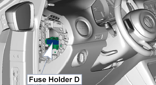
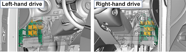
Fuse Box Location (D)
The fuses are on the left side of the dash panel behind a cover.
Fuse Box Diagrams (D)
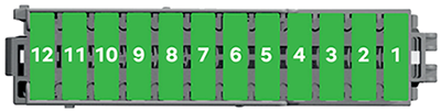
From July 2013
Assignment of fuses in the Fuse Holder D (From July 2013)
| No. | Amps | Description |
|---|---|---|
| 1 | 7.5A | Emergency call module control unit and communication unit |
| 2 | 30A | Brake system pressure accumulator |
| 3 | 7.5A | Ignition key withdrawal lock solenoid valve |
| 4 | 20A | Blower relay |
| 5 | 7.5A | Climatronic relay |
| 6 | 10A | Emergency cut-out connection Maintenance connector for high-voltage system |
| 7 | 20A | Climatronic control unit |
| 8 | 20A | Selector lever Charge voltage control unit for high-voltage battery |
| 9 | 15A | Onboard supply control unit – Dipped beam/daytime running lights/main beam |
| 10 | 15A | Onboard supply control unit – Dipped beam/daytime running lights/main beam |
| 11 | 30A | Heated windscreen relay |
| 12 | 30A | Heated windscreen relay 2 |
From August 2016
Assignment of fuses in the Fuse Holder D (From August 2016)
| No. | Amps | Description |
|---|---|---|
| 1 | 7.5A | Emergency call module control unit and communication unit |
| 2 | 30A | Brake system pressure accumulator |
| 3 | 7.5A | Ignition key withdrawal lock solenoid valve |
| 4 | 20A | Blower relay |
| 5 | 7.5A | Climatronic relay |
| 6 | 10A | Emergency cut-out connection Maintenance connector for high-voltage system |
| 7 | 7.5A | Climatronic control unit |
| 8 | 7.5A | Selector lever Rain and light sensor Charge voltage control unit for high-voltage battery |
| 9 | 15A | Onboard supply control unit – Dipped beam/daytime running lights/main beam |
| 10 | 15A | Onboard supply control unit – Dipped beam/daytime running lights/main beam |
| 11 | 30A | Heated windscreen relay |
| 12 | 30A | Heated windscreen relay 2 |
Relay Box Location
Relay Box Diagram
Assignment of relays in the passenger compartment relay box
| No. | Description |
|---|---|
| 1 | Terminal 75 voltage supply relay 1 |
| 2 | Terminal 15 voltage supply relay |
| 3 | Heated windscreen relay |
| 4 | Main relay |
| 5 | – |
| 6 | Heated windscreen relay 2 |
| 7 | Climatronic relay |
| 8 | – |
| 9 (left) | Daytime running light switch-on relay (According to equipment; applicable from August 2016 up to November 2016) |
| 9 (right) | – |
| 10 | Blower relay |
| 11 | – |
| 12 | – |