Looking for Volkswagen Golf eHybrid fuse box diagrams? This article covers the plug-in hybrid eighth-generation Volkswagen Golf eHybrid (Model Code: CD1), available from 2020, and includes fuse box diagrams for Volkswagen Golf eHybrid (MK8) 2020, 2021, 2022, 2023, 2024, 2025 and 2026, along with details about the location of the fuse panels inside the vehicle and a clear explanation of the assignment of each fuse and relay (fuse layout).
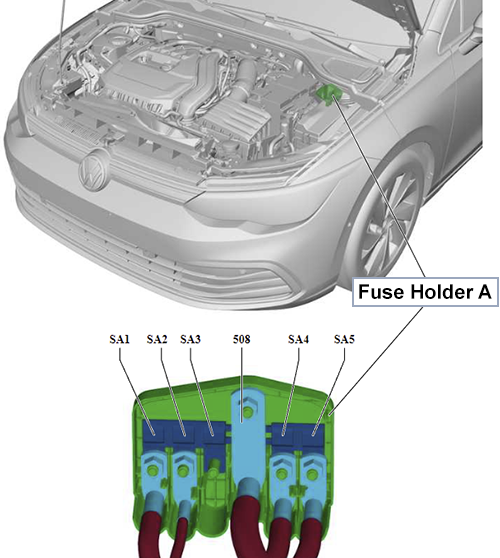
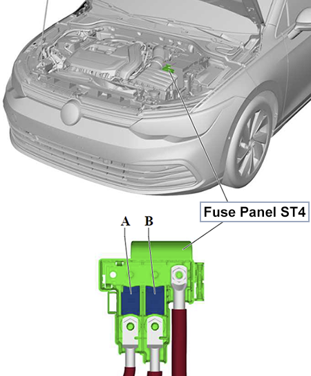
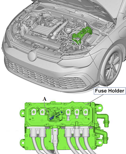
High-voltage system fuse 3 -S353- – Electric Drive Power and Control Electronics -JX1-
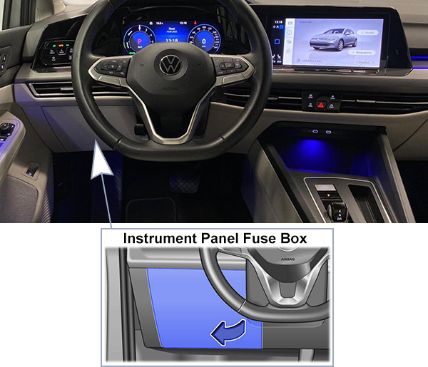
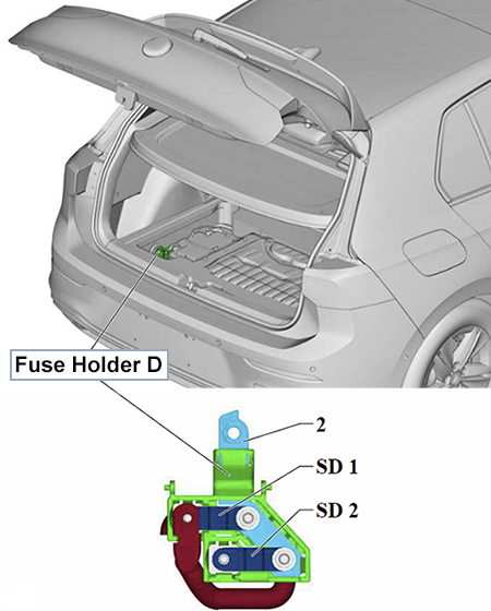
Passenger Compartment
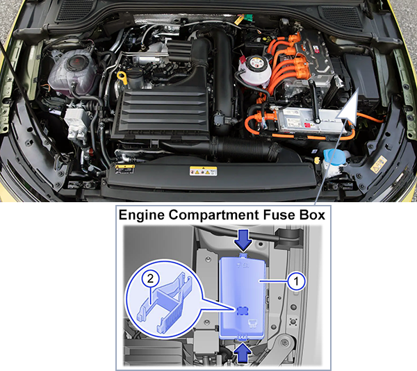
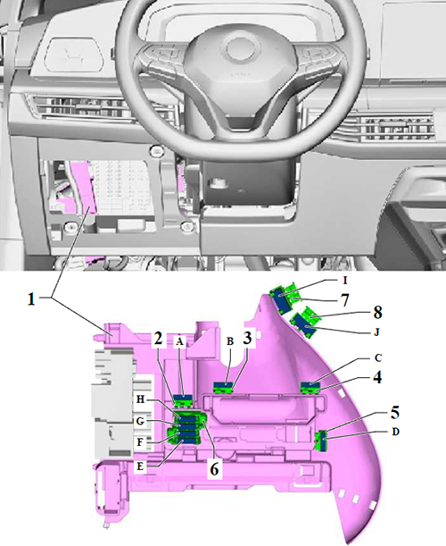
Fuse Box Location (-SC-)
Left-Hand Drive
Left-hand drive vehicles: Reach behind the cover and pull it off in the direction of the arrow.
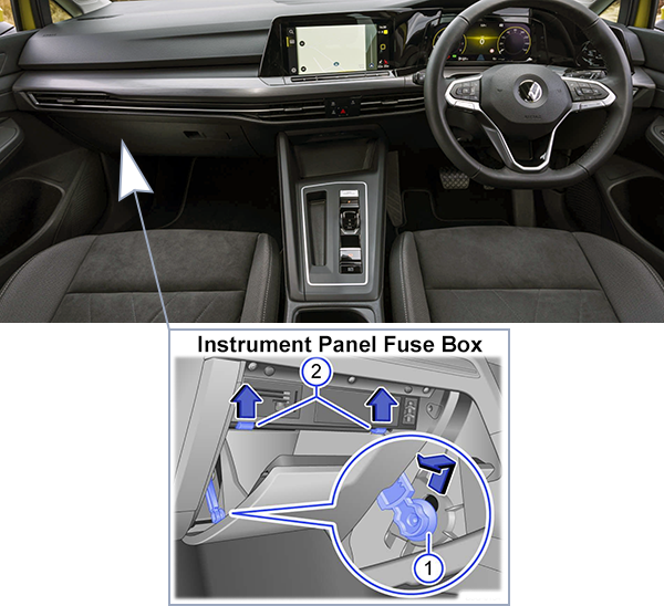
Right-Hand Drive
Right-hand drive vehicles: Push the damper element up and into the opening in the bracket, before pulling it out side-ways (1). Push the catches up in the direction of the arrow while at the same time opening the storage compartment further (2).
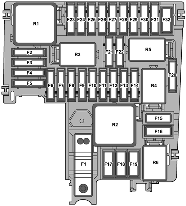
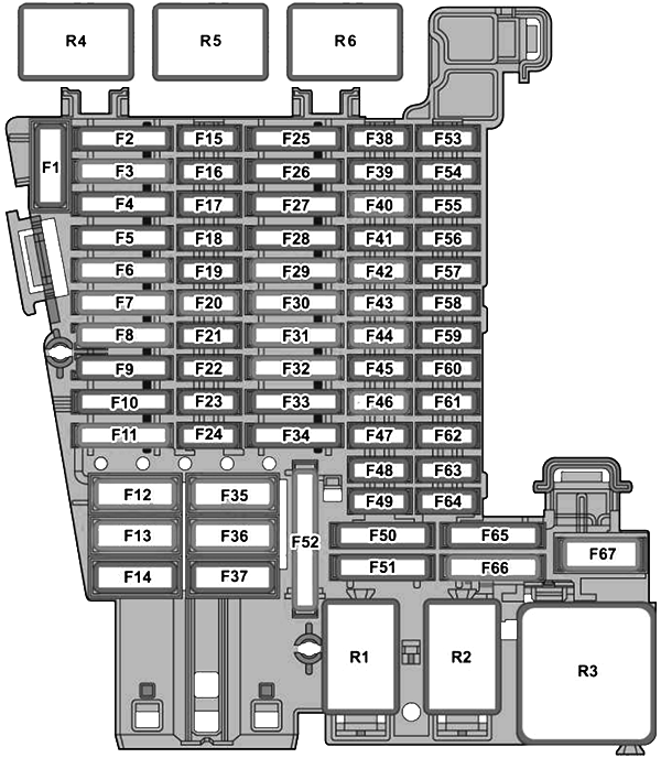
Fuse Box Diagram (-SC-)
Fuses
Assignment of the fuses in passenger compartment (-SC-)
Fuse Data
Full access is available to registered users — log in or register.
Vehicle Electrical System Control Module – interior lighting
SC7
30A
Heating and Air Conditioning Control Module – seat heating
SC8
20A
Sunroof Control Module
SC9
30A
Door Control Modules (Driver, Front Passenger), Rear Window Regulator Motors (Driver Side, Passenger Side)
SC10
–
–
SC11
15A
Towing Recognition Control Module
SC12
40A
Vehicle Electrical System Control Module – exterior lighting (right-side)
SC13
40A
Vehicle Electrical System Control Module – central locking
SC14
30A
Digital Sound System Control Module
SC15
–
–
SC16
7.5A
Airbag Control Module
SC17
–
–
SC18
7.5A
Access/Start Authorization Control Module, Exterior Door Handles (Driver, Front Passenger), Burglary Protection Control Modules 2-5, Electronic Steering Column Lock Control Module
SC19
7.5A
Instrument Cluster, Control Module for Emergency Call Module and Communication Unit
SC20
7.5A 10A
Internet Access Control Module (7.5A), USB Connection 1 (7.5A), Telephone Baseplate (7.5A), Transceiving Stabilization Control Module (7.5A), TV Tuner (7.5A), Chip Card Reader Control Module (7.5A) from Jul 2022: adds USB Charging Socket 1 (10A)
SC21
7.5A
Lane Change Assistance Control Module 1 and 2, Exterior Rearview Mirrors (Driver, Front Passenger), Rear Lid Handle
SC22 – SC23
–
–
SC24
–
up to Jun 2021: Not Assigned
15A
from Jul 2021: All Wheel Drive Control Module
SC25
25A
Front Seat Belts (Left, Right)
SC26
30A
Door Control Modules (Driver, Front Passenger), Rear Window Regulator Motors (Driver Side, Passenger Side)
SC27
25A
Front Seat Belts (Right, Left)
SC28
10A
High-Voltage System Maintenance Connector, High-Voltage Battery 1
SC29
–
–
SC30
30A
Information Electronics Control Module 1
SC31
–
–
SC32
25A
Rear A/C Display Control Head – rear seat heating
SC33 – SC34
–
–
SC35
40A
Vehicle Electrical System Control Module – exterior lighting (left-side)
SC36
40A
Fresh Air Blower Control Module
SC37 – SC38
–
–
SC39
10A
Steering Column Electronics Control Module
SC40
7.5A
Alarm Horn
SC41
7.5A
Data Bus on Board Diagnostic Interface
SC42
7.5A
Selector mechanism, Selector Lever Transmission Range Display
SC43
10A
Vehicle Interior Temperature Sensor, Parking Heater Radio Receiver, Heating and Air Conditioning Control Module, Rear A/C Display Control Head, Rear Window Defogger Relay
SC44
7.5A
Parking brake button, Diagnostic Connection, Front Roof Module, Anti-Theft Alarm System Sensor, Illumination Control Head, Cornering Lamp and Headlamp Range Control Module, Rain/Light Recognition Sensor
SC45
7.5A
Steering Column Electronics Control Module
SC46
7.5A
Windshield Projection Head Up Display Control Module, Front Information Display Control Head
SC47
10A
Electronic Damping Control Module
SC48
7.5A
up to Jun 2022: USB Charging Socket 1
–
from Jul 2022: Not Assigned (moved to SC20)
SC49 – SC51
–
–
SC52
20A
12 V Socket, 12 V Socket 3
SC53 – SC57
–
–
SC58
7.5A
Driver Assistance Systems Front Camera, Parking Aid Control Module, Control Module for Adaptive Cruise Control
Driver Power Seat Adjustment Circuit Breaker 1 -S44- – Driver Seat Adjustment Control Module -J810-
B
–
C
–
D
–
E
–
F
–
G
–
H
–
I
15A
Driver Power Seat Adjustment Circuit Breaker 1 -S44- – Driver Seat Backrest Blower Fan -V388- – Driver Seat Cushion Blower Fan -V390-
J
15A
Front Passenger Power Seat Adjustment Circuit Breaker 1 -S46- – Front Passenger Seat Backrest Blower Fan -V389- – Front Passenger Seat Cushion Blower Fan -V391-
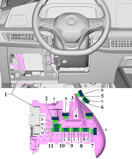
From February 2021
Assignment of the individual fuses in passenger compartment (From February 2021/LHD)
Fuse Data
Full access is available to registered users — log in or register.
Driver Power Seat Adjustment Circuit Breaker 1 (Driver Seat Adjustment Control Module)
B – C
–
–
D
15A
Driver Power Seat Adjustment Circuit Breaker 1: Driver Seat Backrest and Cushion Blower Fan, Driver Seat Adjustment Control Head (USA)
E
15A
Front Passenger Seat Backrest Blower Fan (seat ventilation), Front Passenger Seat Cushion Blower Fan, Front Passenger Seat Adjustment Control Head (USA)
F
–
–
G
10A
Driving assistance and special purpose vehicles: Fuse 1 on Relay and Fuse Panel SRSE: Special Purpose Vehicle Control Module, Diagnostic Connection 2, Wheelchair Lift Coupling Point, Two-Way Radio Coupling Point, Left and Right Front Door Coupling Point, Coupling Point for Event Data Recorder, Special Signal Control Head Coupling Point
H – J
–
–
K
40A
Driving assistance and special purpose vehicles: Fuse 1 on Relay and Fuse Panel SRSC: Wheelchair Lift Coupling Point, Special Purpose Vehicle Control Module
L
40A
Driving assistance and special purpose vehicles: Fuse 2 on Relay and Fuse Panel SRSC: Special Purpose Vehicle Control Module, Fuse 16 on Relay and Fuse Panel SRSH
M – P
–
–
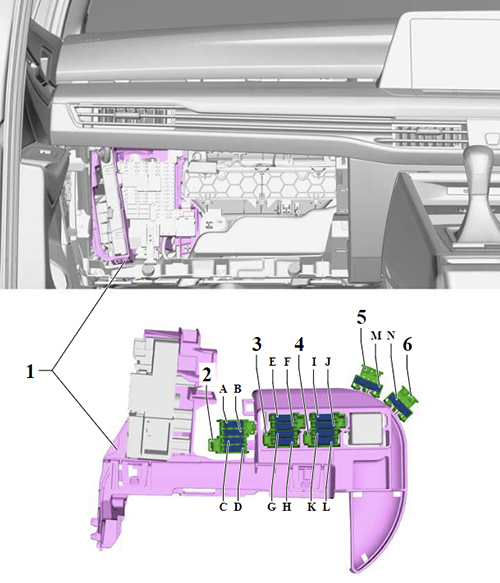
Right-Hand Drive
Assignment of the individual fuses in passenger compartment (RHD)
Fuse Data
Full access is available to registered users — log in or register.
")
")
")
")