
Looking for Volkswagen Phaeton fuse box diagrams? This article covers the luxury sedan Volkswagen Phaeton (Model Codes: GP0, GP1, GP2, GP3, GP4), produced from 2002 to 2016, and includes fuse box diagrams for Volkswagen Phaeton 2004, 2005, 2006, 2007, 2008, 2009, 2010, 2011, 2012, 2013, 2014, 2015 and 2016, along with information about the location of the fuse panels inside the vehicle and a clear explanation of the assignment of each fuse and relay (fuse layout).
What’s Included
ToggleFuse Box Overview
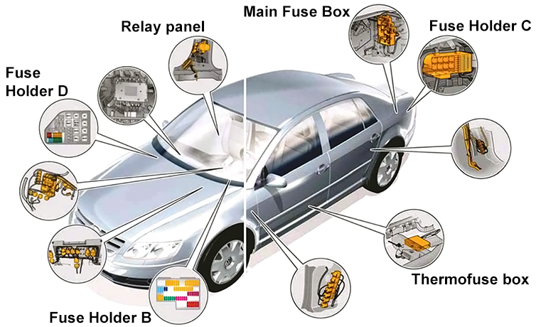
Passenger Compartment
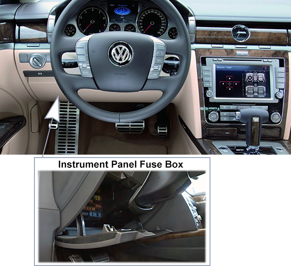
Dashboard (-SB-)
Fuse Box Location
Fuse Box Diagram
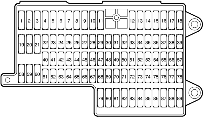
Fuses
Assignment of the fuses in the instrument panel
| No. | Amps | Description |
|---|---|---|
| SB1 | 10A | Terminal 30 for J582 – Wiper Park Position Pleating Relay Z20 – Left Washer Nozzle Pleater Z21 – Right Washer Nozzle Pleater |
| SB2 | 20A 15A | J386 – Door control module, driver side J657 – Door Closing Control Module J388 – Door control module, rear, left |
| SB3 | 20A 15A | J387 – Door control module, passenger side J657 – Door Closing Control Module J389 – Door control module, rear, right |
| SB4 | 20A | SC18 – Fuse 18 (in fuse holder C) SC19 – Fuse 19 (in fuse holder C) SC20 – Fuse 20 (in fuse holder C) |
| SB5 | 5A | J528 – Roof Electronics Control Module |
| SB6 | – | – |
| SB7 | 15A | – |
| SB8 | 25A | J104 – ABS Control Module (w/EDL) J106 – ABS Solenoid Valve Relay |
| SB9 | 5A | – |
| SB10 | 15A | J519 – Vehicle Electrical System Control Module M5 – Left Front Turn Signal Light M1 – Left Parking Light |
| SB11 | 15A | J519 – Vehicle Electrical System Control Module M7 – Right Front Turn Signal Light M3 – Right Parking Light |
| SB12 | 15A | J519 – Vehicle Electrical System Control Module J567 – Left Headlight Range Control Module M29 – Left Low Beam Headlight J683 – Left HID Lamp High Beam Control Module M30 – Left High Beam Headlight |
| SB13 | 15A | J519 – Vehicle Electrical System Control Module J568 – Right Headlight Range Control Module M31 – Right Low Beam Headlight J684 – Right HID Lamp Hight Beam Control Module M32 – Right High Beam Headlight |
| SB14 | 20A | J519 – Vehicle Electrical System Control Module H1 – Signal horn/dual tone horn |
| SB15 | 5A | F – Brake Light Switch J605 – Rear Lid Control Module J…- Engine Control Modlue (ECM) J345 – Control Module for towing sensor J104 – ABS Control Module (w/EDL) |
| SB16 | 20A | J162 – Heater Control Module |
| SB17 | 10A | J523 – Front Information Display Control Head Control Module R24 – Antenna Amplifier |
| SB18 | 10A | J527 – Steering Column Electronic Systems Control Module |
| SB19 | 10A | J518 – Access/Start Control Module |
| SB20 | – | – |
| SB21 | – | – |
| SB22 | 5A | J623 – Engine Control Module (ECM) (engine code BAP) J623 – Engine Control Module (ECM) 2 (engine code BAP) J220 – Motronic Engine Control Module (ECM) (engine code BGJ) |
| SB23 | 5A | J285 – Control module with indicator unit in instrument panel insert |
| SB24 | – | – |
| SB25 | – | – |
| SB26 | – | – |
| SB27 | 5A | J285 – Control module with indicator unit in instrument panel insert Data Link Connector (DLC) J669 – Seat Belt Tensioner Relay |
| SB28 | 5A | J526 – Telephone/Telematic Control Module |
| SB29 | 5A | R149 -Auxiliary Water Heating RF Receiver (where applicable) |
| SB30 | 10A | J255 – Climatronic Control Module V50 – Coolant Pump N175 – Left Heat Regulating Valve N176 – Right Heat Regulating Valve |
| SB31 | 5A | Y – Analog Clock/Control Module J524 – Rear Information Display Control Head |
| SB32 | – | – |
| SB33 | 5A | J401 – Control module for navigation with CD-mechanism |
| SB34 | 5A | H8 – Alarm Horn |
| SB35 | 5A | J519 – Vehicle Electrical System Control Module |
| SB36 | 10A | J519 – Vehicle Electrical System Control Module |
| SB37 | 5A | J526 – Telephone/Telematic Control Module |
| SB38 | – | – |
| SB39 | – | – |
| SB40 | 5A | J519 – Vehicle Electrical System Control Module |
| SB41 | 5A | J518 – Access/Start Control Module |
| SB42 | – | – |
| SB43 | – | – |
| SB44 | – | – |
| SB45 | – | – |
| SB46 | – | – |
| SB47 | – | – |
| SB48 | – | – |
| SB49 | – | – |
| SB50 | – | – |
| SB51 | – | – |
| SB52 | 5A | J669 – Seat Belt Tensioner Relay |
| SB53 | 5A | F47 – Brake Pedal Switch (cruise control) G42 – Intake Air Temperature (IAT) Sensor (engine code BGJ) G70 – Mass Air Flow (MAF) Sensor (engine code BGJ) G246 – Mass Air Flow (MAF) Sensor 2 (engine code BGJ) J569 – Brake Booster Relay |
| SB54 | 5A | J285 – Control module with indicator unit in instrument panel insert |
| SB55 | 10A | J234 – Airbag Control Module J623 – Engine Control Module (ECM) (engine code BAP) J623 – Engine Control Module (ECM) 2 (engine code BAP) J220 – Motronic Engine Control Module (ECM) (engine code BGJ) |
| SB56 | 5A | G266 – Oil Level Thermal Sensor |
| SB57 | – | – |
| SB58 | 15A | L22 – Left Front Fog Light L23 – Right Front Fog Light |
| SB59 | 10A | N79 – Positive Crankcase Ventilation (PCV) Heating Element (where applicable) |
| SB60 | 15A 5A | E301 – Left Front Air Outlet Button E302 – Left Front (Center) Air Outlet Button E303 – Right Front (Center) Air Outlet Button E304 – Right Front Air Outlet Button E305 -Footwell/Cabin Temperature Differential Button E306 – Left Rear Center Console Air Outlet Button E307 – Right Rear Center Console Air Outlet Button |
| SB61 | 5A | J104 – ABS Control Module (w/EDL) |
| SB62 | – | – |
| SB63 | 5A | J519 – Vehicle Electrical System Control Module E1 – Light Switch J567 – Left Headlight Range Control Module J568 – Right Headlight Range Control Module J526 – Telephone/Telematic Control Module J539 – Brake Booster Control Module G258 – Left Distance Regulation Sensor G259 – Right Distance Regulation Sensor J428 – Control Module for Distance Regulation |
| SB64 | 5A | J527 – Steering Column Electronic Systems Control Module |
| SB65 | 10A | V55 – Recirculation Pump |
| SB66 | 5A | J262 – Rear Window Shade Control Module N280 – A/C Compressor Regulator Valve J255 – Climatronic Control Module |
| SB67 | 10A | F189 -Tiptronic Switch F319 – Selector Lever Park Position Lock Switch F125 – Multi-Function Transmission Range (TR) Switch J217 – Transmission Control Module (TCM) E256 -ASR/ESP Button |
| SB68 | 5A | N110 – Shift Lock Solenoid |
| SB69 | – | – |
| SB70 | 5A | J236 – Servotronic Control Module |
| SB71 | 10A 5A | J131 – Driver’s Heated Seat Control Module J132 – Passenger’s Heated Seat Control Module |
| SB72 | 5A | G238 -Sensor for Air Quality |
| SB73 | – | – |
| SB74 | – | – |
| SB75 | – | – |
| SB76 | – | – |
| SB77 | – | – |
| SB78 | 5A | F47 – Brake Pedal Switch (cruise control) (where applicable) |
| SB79 | 15A | U18 – 12V outlet -2- (in center console), front |
| SB80 | 15A | U19 – 12V outlet -3- (in center console, rear) |
| SB81 | 30A | J245 – Power Sunroof Control Module |
| SB82 | – | – |
| SB83 | 20A | J525 – Digital Sound System Control Module |
| SB84 | 15A | U1 – Cigarette Lighter |
| SB85 | 15A | U3 – Left Rear Cirgarette Lighter |
| SB86 | 15A | U7 – Right Rear Cigarette Lighter |
| SB87 | 30A/15A | J136 – Memory Seat/Steering Column Adjustment Control Module J131 – Driver’s Heated Seat Control Module |
| SB88 | 30A/15A | J521- Passenger Memory Seat Control Module J132- Passenger’s Heated Seat Control Module |
| SB89 | 30A | J522- Rear Memory Seat Control Module |
Thermofuse Box (-SE-)
Fuse Box Location
Fuse box is located in driver side footwell.
Fuse Box Diagram
Fuses
Assignment of the fuses in the thermofuse box
| No. | Amps | Description |
|---|---|---|
| SE1 | 30A | J386 – Door control module, driver side J388- Door control module, rear, left |
| SE2 | 30A | J387 – Door control module, passenger side J389- Door control module, rear, right |
| SE3 | 30A | J136 – Memory Seat/Steering Column Adjustment Control Module |
| SE4 | 30A | J521 – Passenger Memory Seat Control Module |
| SE5 | 30A | J522 – Rear Memory Seat Control Module |
| SE6 | 30A | Z42 – Left Rear Footwell Heater |
| SE7 | 30A | Z43 – Right Rear Footwell Heater |
| SE8 | – | – |
| SE9 | – | – |
| SE10 | – | – |
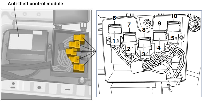
Relay Box
Relay Box Location
Relay box is located in front passenger side footwell.
Relay Box Diagram
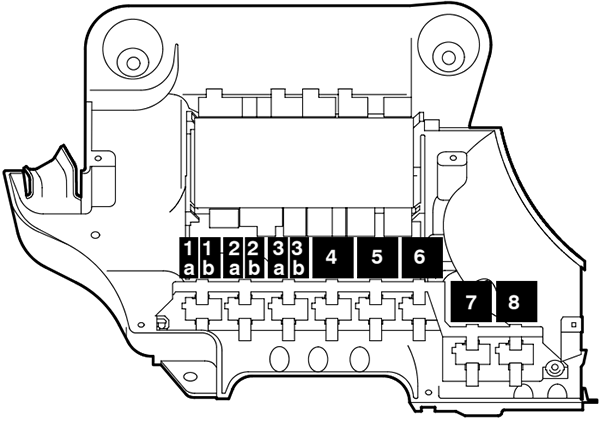
Relays
Assignment of the relays
| No. | Description |
|---|---|
| 1a | -J496 – Auxiliary Engine Coolant (EC) Pump Relay (404) |
| 1b | – |
| 2a | – |
| 2b | – |
| 3a | -J582 – Wiper Park Position Heating Relay (404) |
| 3b | – J709 – Seat Heater Authorization Relay (404) |
| 4 | – J309 – Solar Cell Separation Relay (79) |
| 5 | – J681 – Power Supply Relay 2 (terminal 15) (100) |
| 6 | – J39 – Relay for headlamp cleaning system (53) |
| 7 | – J236 – Servotronic Control Module (631) |
| 8 | – J669 – Seat Belt Tensioner Relay |
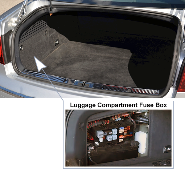
Luggage Compartment
Fuse Box Location
Fuse box is located on the left side in the luggage compartment under the lid.
Fuse Box Diagram (-S-)
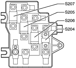
High Voltage Fuses
Assignment of the high voltage fuses
| No. | Amps | Description |
|---|---|---|
| S204 | 100A | A18- Windshield Heating Voltage Converter |
| S205 | 150A | TV28- Wire junction 3 for terminal 30, Thermofuses: SE1, SE2, SE3, SE4, SE5, SE6, SE7 Fuses: SB5, SB7 to SB18, SB27 to SB36, SD11, SD23, SD24, SD26, J329- Voltage Supply Terminal 15 (B+) Relay J680- Power Supply Relay 1 (terminal 75) |
| S206 | 300A | Fuses: SC3, SC6, SC8 to SC16, SC23 to SC27, SC41 to SC47 C – Generator (GEN) |
| S207 | – | – |
Fuse Box Diagram (-SC-)
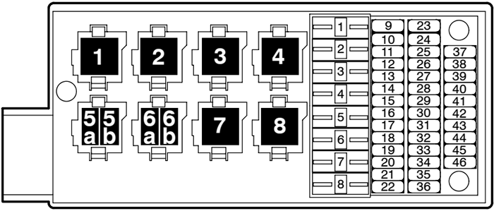
Fuses
Assignment of the fuses in the luggage compartment
| No. | Amps | Description |
|---|---|---|
| SC1 | 60A | Terminal 30 for J682 – Power Supply Relay (terminal 50) B – Starter (termnial 50) J367- Battery Monitoring Control Module J581- Parallel Battery Connection Relay J623- Engine Control Module (ECM) (engine code BAP) J220- Motronic Engine Control Module (ECM) (engine code BGJ) |
| SC2 | 80A | Terminal 30 for J580 – Starter Battery Switch-over Relay J367- Battery Monitoring Control Module |
| SC3 | 80A | Terminal 30 for J579 – Electrical System Battery Switch-over Relay J367- Battery Monitoring Control Module |
| SC4 | – | – |
| SC5 | – | – |
| SC6 | 40A | Terminal 30 for J403 – Relay for compressor level control system V66 – Motor for compressor-level control system |
| SC7 | – | – |
| SC8 | 80A | Fuses SB2, SB3, SB37, SB39, SB41, SB79, SB80, SB81, SB83, SB84, SB85, SB86, SB87, SB88, SB89 |
| SC9 | 30A | T13 – 13-Pin Connection (for U10 – Trailer Socket – where applicable) |
| SC10 | 5A | J367- Battery Monitoring Control Module |
| SC11 | 5A | J502- Tire Pressure Monitoring Control Module |
| SC12 | 5A | J446- Control module for parking aid |
| SC13 | 30A | J345- Control Module for towing sensor (where applicable) |
| SC14 | 5A | J677- Fuel Filler Lid Unlock Relay V155- Motor for fuel tank lid unlock |
| SC15 | 25A | J679- Pleated Rear Window Circuit 2 Relay Z1 – Pleated rear window |
| SC16 | 25A | J678- Pleated Rear Window Circuit 1 Relay Z3 – 2nd Stage Rear Window Pleater Element |
| SC17 | – | – |
| SC18 | 5A | J393 – Central control module for comfort system J690 – Left Rear Tail Light Control Module J691 – Right Rear Tail Light Control Module |
| SC19 | 5A | J197- Level Control System Control Module |
| SC20 | 5A | J345- Control Module for towing sensor (where applicable) |
| SC21 | – | – |
| SC22 | 5A | – |
| SC23 | 5A | W3- Luggage compartment light Illumination for E406 – Rear Lid Lock Button (in luggage compartment) |
| SC24 | 10A | J393- Central control module for comfort system |
| SC25 | 5A | J262- Rear Window Shade Control Module V91- Rear Window Shade Motor |
| SC26 | 10A | J393- Central control module for comfort system |
| SC27 | 15A | U5- 12 V Socket (in luggage compartment, left) |
| SC28 | – | – |
| SC29 | – | – |
| SC30 | – | – |
| SC31 | – | – |
| SC32 | 5A | J581- Parallel Battery Connection Relay |
| SC33 | 5A | J17 – Fuel Pump (FP) Relay J271 – Motronic Engine Control Module (ECM) Power Supply Relay J670 – Motronic Engine Control Module (ECM) Power Supply Relay 2 J581 – Parallel Battery Connection Relay (where applicable) J49 – Fuel Pump (FP) 2 Rela y J220- Motronic Engine Control Module (ECM) (engine code BGJ) |
| SC34 | 20A | G6 – Fuel Pump (FP) |
| SC35 | 20A | G23 – Transfer Fuel Pump (FP) |
| SC36 | 30A | Terminal 30 for J681 – Power Supply Relay 2 (terminal 15) Fuses: SB52, SB53, SB54, SB55, SB56, SB57 |
| SC37 | – | – |
| SC38 | – | – |
| SC39 | – | – |
| SC40 | – | – |
| SC41 | 5A | G384- Vehicle Inclination Sensor |
| SC42 | 5A 15A 1 | J393- Central control module for comfort system |
| SC43 | 30A | J605- Rear Lid Control Module |
| SC44 | 10A | J197- Level Control System Control Module |
| SC45 | 5A | J697- License Plate Light Control Module L153- Rear Illumination Lamp |
| SC46 | – | – |
Relays
Assignment of the relays in the luggage compartment
| No. | Description |
|---|---|
| 1 | – J579 – Electrical System Battery Switch-over Relay (432) |
| 2 | – J580 – Starter Battery Switch-over Relay (100) |
| 3 | – J682 – Power Supply Relay (terminal 50) (433) |
| 4 | – J678 – Heated Rear Window Circuit 1 Relay (100) |
| – J678 – Heated Rear Window Circuit 1 Relay (53) | |
| 5a | – J17 – Fuel Pump (FP) Relay (404) |
| 5b | – J677 – Fuel Filler Lid Unlock Relay (404) |
| 6a | – |
| 6b | – J49 – Fuel Pump (FP) 2 Relay (404) |
| 7 | – J403 – Relay for compressor level control system (214) |
| 8 | – J679 – Heated Rear Window Circuit 2 Relay (100) |
| – J679 – Heated Rear Window Circuit 2 Relay (53) |
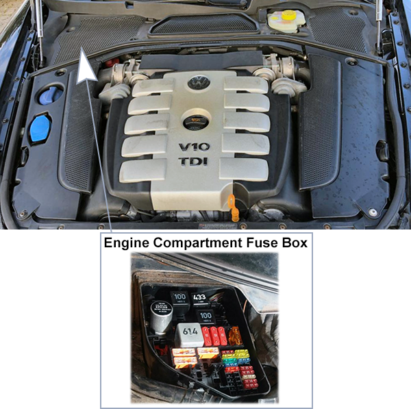
Engine Compartment (-SD-)
Fuse Box Location
The Fuse Box is located on the passenger side in the corner of engine compartment, near the windshield.
Fuse Box Diagram
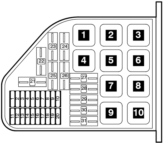
Fuses
Assignment of the fuses in the right plenum chamber
| No. | Amps | Description |
|---|---|---|
| SD1 | 10A | N… – Fuel Injectors for cylinders 1 – 6 (engine code BAP) |
| SD2 | 10A | N… – Fuel Injectors for cylinders 7 -12 (engine code BAP) |
| SD3 | 30A | – |
| SD4 | 30A | – |
| SD5 | 5A | G70 – Mass Air Flow (MAF) Sensor (engine code BAP) G246 – Mass Air Flow (MAF) Sensor 2 (engine code BAP) G42 – Intake Air Temperature (IAT) Sensor (engine code BAP) G299 – Intake Air Temperature (IAT) Sensor 2 (engine code BAP) |
| SD6 | 10A | J496 – Auxiliary Engine Coolant (EC) Pump Relay (engine code BAP) V51 – After-Run Coolant Pump (engine code BAP) J299 – Secondary Air Injection (AIR) Pump Relay J545 – Secondary Air Injection (AIR) Pump Relay 2 (code BAP) J49 – Fuel Pump (FP) 2 Relay (engine code BAP) V36 – Coolant Pump (engine code BGJ) J151- Coolant Circulation Pump Relay (engine code BGJ) |
| SD7 | 20A | F265 – Map Controlled Engine Cooling Thermostat (en-code BAP) N80 – Evaporative Emission (EVAP) Canister Purge Regulator Valve N112 – Secondary Air Injection (AIR) Solenoid Valve N145 – Right Electro-Hydraulic Engine Mount Solenoid Valve (code BAP) N156 – Intake Manifold Change-Over Valve (engine code BGJ) N205 – Valve -1- for camshaft adjustment N208 – Valve -2- for camshaft adjustment N261 – Intake Manifold Tuning (IMT) Valve -2- (engine code BGJ) N318 – Camshaft Adjustment Valve 1 (exhaust) (engine code BAP) N319 – Camshaft Adjustment Valve 2 (exhaust) (engine code BAP) N320 – Secondary Air Injection (AIR) Solenoid Valve 2 (en-code BAP) N333 – Evaporative Emission (EVAP) Canister Purge Regulator Valve 2 (engine code BAP) |
| SD8 | 30A | N… – Ignition Coils with Power Output Stage for cylinders 1 – 8 (engine code BGJ) |
| SD9 | 20A | N… – Fuel Injectors for cylinders 1 – 8 (engine code BGJ) |
| SD10 | 10A | J623 – Engine Control Module (ECM) (engine code BAP) J624 – Engine Control Module (ECM) 2 (engine code BAP) J220 – Motronic Engine Control Module (ECM) (engine code BGJ) |
| SD11 | 15A | J39 – Relay for headlamp cleaning system |
| SD12 | 10A | J293 – Coolant FC (Fan ControK (FC)) Control Module V7 – Coollant Fan J671 – Coolant FC (Fan Control) Control Module 2 V177 – Coolant Fan 2 |
| SD13 | 25A | Z19 – Oxygen Sensor (O2S) Pleater (engine code BAP) Z28 – Oxygen Sensor (O2S) 2 Heater 2 (engine code BAP) Z29 – Oxygen Sensor (O2S) Heater 1 (behind Three Way Catalytic Converter (TWC)) (engine code BAP) Z30 – Oxygen Sensor (O2S) Heater 2 (behind Three Way Catalytic Converter (TWC)) (engine code BAP) |
| SD14 | 25A | Z19 – Oxygen Sensor (O2S) Heater (engine code BGJ) Z28 – Oxygen Sensor (O2S) 2 Heater 2 (engine code BGJ) Z29 – Oxygen Sensor (O2S) Heater 1 (behind Three Way Catalytic Converter (TWC)) (engine code BGJ) Z30 – Oxygen Sensor (O2S) Heater 2 (behind Three Way Catalytic Converter (TWC)) (engine code BGJ) Z62 – Oxygen Sensor (O2S) Heater 3 (engine code BAP) Z63 – Oxygen Sensor (O2S) Heater 4 (engine code BAP) Z64 – Oxygen Sensor (O2S) Heater 3 (behind Three Way Catalytic Converter (TWC)) (engine code BAP) Z65 – Oxygen Sensor (O2S) Heater 4 (behind Three Way Catalytic Converter (TWC)) (engine code BAP) |
| SD15 | 15A | J217 – Transmission Control Module (TCM) |
| SD16 | 10A | J539 – Brake Booster Control Module |
| SD17 | 5A | J309 – Solar Cell Separation Relay |
| SD18 | 15A | J519 – Vehicle Electrical System Control Module V248 – Left Headlight Washer Jet Motor V249 – Right Headlight Washer Jet Motor |
| SD19 | 20A | J400 – Control module for wiper motor V216 – Left Windshield Wiper Motor V59 – Windshield and Rear Window Washer Pump |
| SD20 | 20A | J584 – Right Windshield Wiper Motor Control Module V217 – Right Windshield Wiper Motor |
| SD21 | 60A | Vehicles with single battery system only: SB19 – Fuse 19 (in fuse holder B) SB20 – Fuse 20 (in fuse holder B) SB22 – Fuse 22 (in fuse holder B) SB23 – Fuse 23 (in fuse holder B) Terminal 30 for J271 – Motronic Engine Control Module (ECM) Power Supply Relay |
| SD22 | 40A | SD1 – Fuse 1 (in fuse holder) (engine code BAP) N… – Ignition Coils with Power Output Stage for cylinders 1 – 6 (engine code BAP) |
| SD23 | 40A | Terminal 30 fur J680 – Power Supply Relay 1 (terminal 75) SB1 – Fuse 1 (in fuse holder B) SB40 – Fuse 40 (in fuse holder B) |
| SD24 | 40A | J104 – ABS Control Module (w/EDL) |
| SD25 | 40A | SD2 – Fuse 2 (in fuse holder) (engine code BAP) N… – Ignition Coils with Power Output Stage for cylinders 7-12 (engine code BAP) |
| SD26 | 40A | Terminal 30 for J329 – Voltage Supply Terminal 15 (B+) Relay |
| SD27 | 50A | J293 – Coolant FC (Fan ControK (FC)) Control Module (left) |
| SD28 | 50A | J671 – Coolant FC (Fan Control) Control Module 2 (right) |
| SD29 | 50A | V101 – Secondary Air Injection (AIR) Pump Motor |
| SD30 | 50A | V189 – Secondary Air Injection (AIR) Pump Motor 2 (engine code BAP) |
| SD31 | 40A | V2 – Fresh Air BLower J255 – Climatronic Control Module Terminal 87 for J309 – Solar Cell Separation Relay |
Relays
Assignment of the relays in the right plenum chamber
| No. | Description |
|---|---|
| 1 | – |
| 2 | – C24 – Supressor |
| 3 | – J682- Power Supply Relay (terminal 50) |
| 4 | – J271 – Motronic Engine Control Module (ECM) Power Supply Relay (167) |
| 5 | – J670 – Motronic Engine Control Module (ECM) Power Supply Relay 2 (100) (engine code BAP) |
| 6 | – J680 – Power Supply Relay 1 (terminal 75) (100) |
| 7 | – J299 – Secondary Air Injection (AIR) Pump Relay (100) |
| 8 | – J329 – Voltage Supply Terminal 15 (B+) Relay (433) (where applicable) |
| 9 | – J545 – Secondary Air Injection (AIR) Pump Relay 2 (100) (engine code BAP) |
| 10 | – |