Mercedes-Benz CLA-Class Fuse Box Locations and Diagrams (2013-2019)
The first-generation Mercedes-Benz CLA-Class (C117 – four-door coupe; X117 – Shooting Brake) was produced from 2013 to 2019. Designed as a stylish, entry-level luxury model, the CLA blended sporty aesthetics with practicality, offering a range of engines and trims, including the high-performance AMG variant.
In this article, you will find fuse box diagrams for the Mercedes-Benz CLA-Class, covering models CLA180, CLA200, CLA220, CLA250, and CLA45 AMG for the years 2013, 2014, 2015, 2016, 2017, 2018, and 2019. These diagrams provide essential information on the fuse layout, allowing you to locate and understand the purpose of each fuse and relay in your vehicle.
What’s Included in This Guide:
Fuse Box Diagrams – Clear visuals showing the layout of each fuse panel, with numbered fuses and relay placements.
Fuse Panel Locations – Instructions on how to find the fuse boxes inside the vehicle, including areas like the passenger footwell, engine bay, and luggage compartment.
Fuse Assignments – A full list of fuse functions to help diagnose and fix electrical issues related to lighting, power windows, infotainment, engine control, and more.
Whether you’re troubleshooting a malfunction, replacing a blown fuse, or upgrading your CLA’s electrical systems, this guide is an essential tool.
Stay in control of your Mercedes-Benz CLA-Class (2013–2019) with this complete reference to fuse box locations, layouts, and relay functions.
The cigar lighter (power outlet) fuses in the Mercedes-Benz CLA-Class are:
Passenger Compartment Fuse Box.
Fuse №70: Rear Center Console Socket
Fuse №71: Luggage Compartment Socket
Fuse №73: Front Cigarette Lighter, Interior Power Outlet
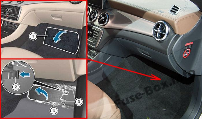
The fuse box is located under the floor near the passenger seat.
Remove the floormats. Fold out perforated floor covering (1) in the direction of the arrow. To release cover (3), press retaining clamp (2). Fold out cover (3) in the direction of the arrow to the catch. Remove cover (3) forwards. Fuse allocation chart (4) is located on the lower right-hand side of cover (3).
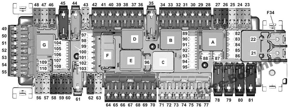
Fuse box diagram
Assignment of the fuses and relay in the passenger compartment
№
Fused function
Amp
21
Valid for diesel engine: PTC heater booster
150
22
Additional battery relay for ECO start/stop function
Front passenger seat occupied recognition and ACSR Weight sensing system (WSS) control unit
7,5
96
Tailgate wiper motor
15
97
Mobile phone electrical connector
5
98
SAM control unit
5
99
Tire pressure monitor control unit
5
100
Valid for engine 133: DIRECT SELECT INTERFACE
5
101
4MATIC: All-wheel drive control unit
10
102
Stationary heater radio remote control receiver Valid for AMG vehicles as of 01.09.2015: Transmission mode control unit as of 01.06.2016: Antenna changeover switch for telephone and stationary heater
5
103
Emergency call system control unit Telematics services communications module HERMES control unit
5
104
Media interface control unit Multimedia connection unit
5
105
Digital Audio Broadcasting control unit Satellite digital audio radio (SDAR) control unit
5
105
Tuner unit
7,5
106
Multifunction camera
5
107
Digital TV tuner
5
108
up to 31.05.2016: Reversing camera
5
108
as of 01.06.2016: Reversing camera
7,5
109
Charging socket electrical connector
20
110
Radio COMAND controller unit Engine sound control unit
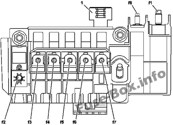
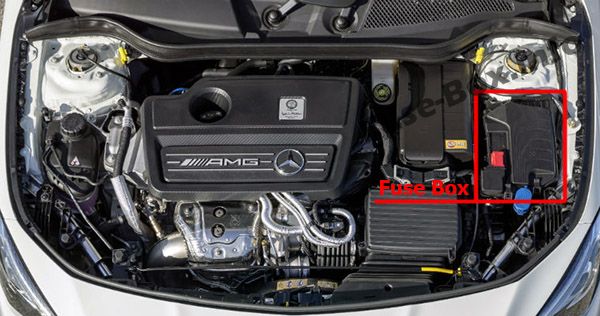
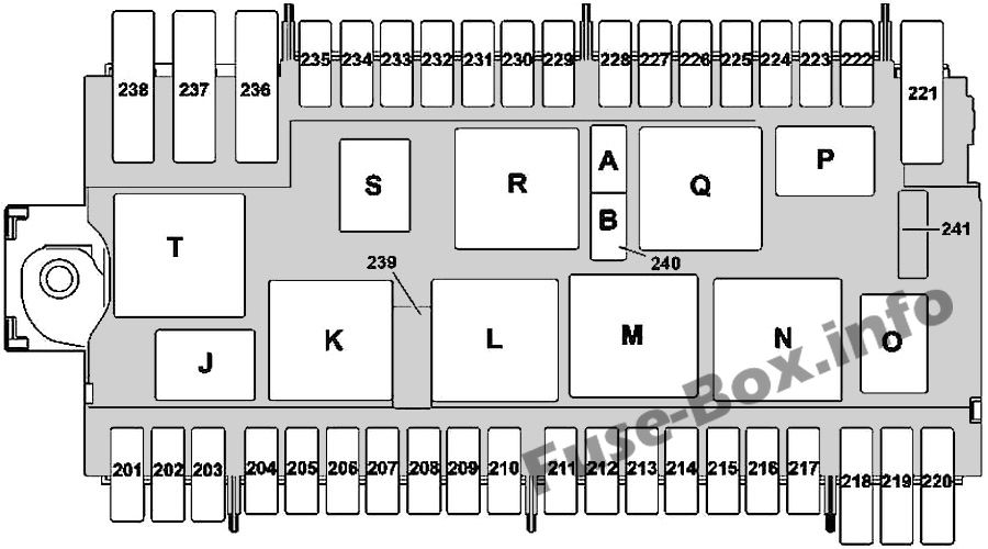
Assignment of the fuses and relay in the engine compartment
№
Fused function
Amp
201
Alarm siren
5
202
Stationary heater control unit
20
203
LED headlamp: Right front lamp unit
15
204
Electronic Stability Program control unit
25
205
Left fanfare horn Right fanfare horn
15
206
Valid for engine 651: CDI control unit Valid for engine 607: Powertrain control unit
5
207
Valid for diesel engine: Circuit relay 87M
5
208
Valid for engine 133, 607: Circuit 87 relay
7.5
209
LED headlamp: Left front lamp unit
15
210
Heated windshield relay
5
211
Not used
–
212
Valid for engine 133, 270: Connector sleeve, circuit 87M3 Valid for engine 651: Vent line heater element Coolant thermostat heating element Exhaust gas recirculation cooler bypass switchover valve Valid for engine 607 (Emissions standard EU5): Oxygen sensor upstream of catalytic converter Boost pressure positioner Valid for engine 607 (Emissions standard EU6): Oxygen sensor upstream of catalytic converter Valid for engine 607: CDI control unit
15
213
Valid for engine 133, 270, 651: Connector sleeve, circuit 87 M2e Valid for engine 607 (Emissions standard EU5): Camshaft Hall sensor CDI control unit Quantity control valve Valid for engine 607 (Emissions standard EU6): Oxygen sensor downstream of catalytic converter CDI control unit