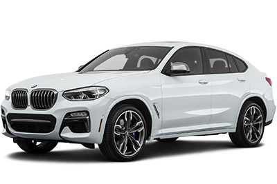
Find BMW X4 fuse box diagrams for 2018–2025 models with fuse locations, panel layouts, and detailed electrical system information for the second-generation Sports Activity Coupe. This article covers the second-generation BMW X4 (Model Code: G02) , available from 2018 , and includes fuse box diagrams for BMW X4 2018, 2019, 2020, 2021, 2022, 2023, 2024 and 2025 , along with details about the location of the fuse panels inside the vehicle and a clear explanation of the assignment of each fuse (fuse layout).
NEED A REPLACEMENT?
Looking for the right fuse or relay?
Search common fuse types, fuse kits and relay options for your vehicle.
Find Fuses & Relays
→
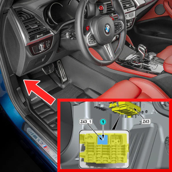
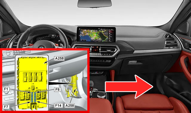
The fuse box is located on the driver’s side (you may need to remove the protective trim—loosen the fasteners, follow the arrows, and open the cover).
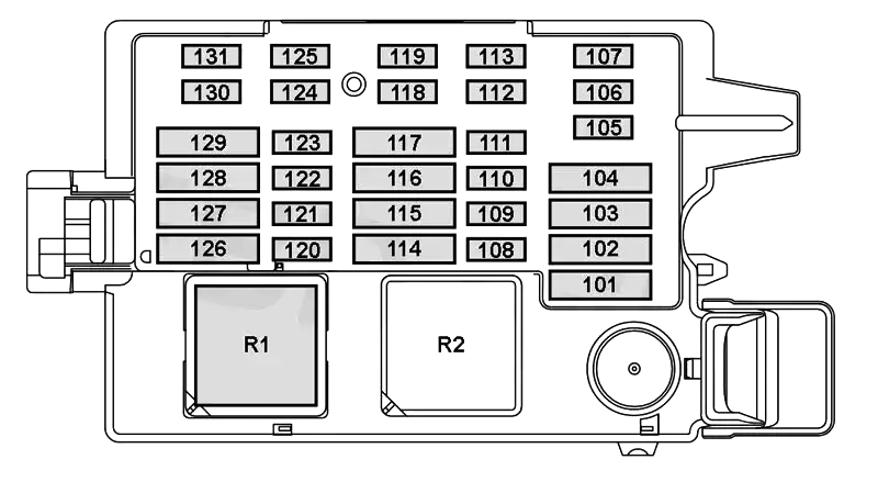
Assignment of the fuses in the passenger compartment (Driver’s side)
Fuse Data
Full access is available to registered users — log in or register.
Log in or register
No. Amps Description 105 7.5A Fuel injection & similar electronics 107 10A Fuel pump relay / Fuel pump control 108 15A Fuel injection & similar electronics 110 5A Heating / Independent aux.heater 111 5A Rear switchboard 117 30A Gear indicator, EDC, Gear Automatic Transmission Control, AWD
This content requires JavaScript and a valid membership to view.
Assignment of the relays in the passenger compartment (Driver’s side)
Fuse Data
Full access is available to registered users — log in or register.
Log in or register
No. Description R1 – R2 Terminal 30B relay
This content requires JavaScript and a valid membership to view.
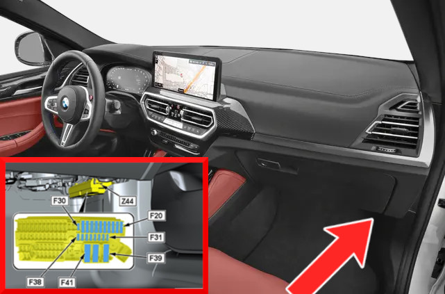
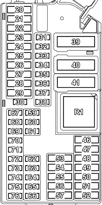
On the right-hand side, beneath the glove box, is the fuse and relay box.
Assignment of the fuses in the passenger compartment (Passenger’s side)
Fuse Data
Full access is available to registered users — log in or register.
Log in or register
No. Amps Description 20 30A Power windows with anti-trapping function 21 30A Power windows with anti-trapping function 22 30A Power windows with anti-trapping function 23 30A Power windows with anti-trapping function 24 30A Seatbelts 25 20A Replacement top module; Alternating relay 26 20A Rear wiper / Headlights, rain sensor, light sensor relay 27 5A Car alarm 28 40A ABS (Anti-lock Brake System), DSC (Dynamic Stability Control), Parking brake 29 20A Headlights, rain sensor, light sensor 32 5A Parking brake, center console control panel 34 5A Instrument cluster 35 5A Gear Indicator / DSC – Dynamic Stability Control / SMG – Sequential Manual Gearbox, Driving assistance, Infotainment 36 5A Car alarm, Replacement top module; Alternating relay, Interior lights 39 60A BDC 40 40A Air conditioning system, Electric fan 46 20A Front & rear cigarette lighter, 12V socket / Glove box charging socket (12V) 47 20A Front & rear cigarette lighter 48 20A Heated seats 51 30A Gear indicator, EDC, Gear Automatic Transmission Control 52 20A Heated seats 53 30A Seat adjustment 55 30A Seat adjustment 57 10A Driving assistance 59 5A Electrochromic rear view mirror, Main headlights / Rain sensor / Light sensor / Electronic ride height control 60 5A Driving assistance 61 5A Load level, Interior lights 62 5A Interior lights 63 5A Air conditioning system 64 5A Seat adjustment 65 5A Seat adjustment 66 5A Interior lights 67 5A Seat adjustment, Electric mirrors, Interior lights 68 5A Electric mirrors, Interior lights 69 5A Electric fan, Fuel injection & similar electronics 70 5A Electric fan, Fuel injection & similar electronics 71 5A Interior lights 73 5A Instrument cluster 74 5A Electric fan 75 10A Seatbelts 76 5A Steering column function control module
This content requires JavaScript and a valid membership to view.
Assignment of the relays in the passenger compartment (Passenger’s side)
Fuse Data
Full access is available to registered users — log in or register.
Log in or register
No. Description R1 Terminal 30B relay
This content requires JavaScript and a valid membership to view.
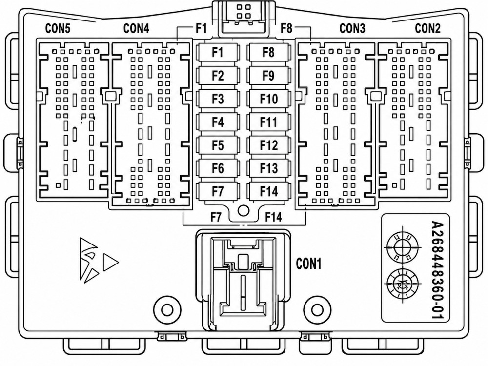
The fuse compartment is located in the BDC (Body Domain Controller) electronic control unit, which is mounted on the right pillar beneath the passenger compartment trim on the passenger’s right side.
Assignment of the fuses in the passenger compartment (Body Domain Controller) Type 1
Fuse Data
Full access is available to registered users — log in or register.
Log in or register
No. Amps Description 1 5A Steering column function control module, Driving assistance, Infotainment, Main headlights / Rain sensor / Light sensor / Electronic ride height control 2 7.5A On-Board Diagnostics (OBD), Air suspension compressor relay, Dynamic drive system, Load level 3 7.5A Air conditioning system, Electric rear sunshade, Tailgate, Main headlights / Rain sensor / Light sensor / Electronic ride height control 4 5A Infotainment, Door module / Automatic soft-close, Start-Stop system 5 20A Door module / Automatic soft-close 6 20A Door module / Automatic soft-close 7 15A Horn
This content requires JavaScript and a valid membership to view.
Assignment of the fuses in the passenger compartment (Body Domain Controller) Type 2
Fuse Data
Full access is available to registered users — log in or register.
Log in or register
No. Amps Description 4 20A Lock relay, unlock relay (doors, fuel filler cap) 6 20A Driver’s door lock relay, lock relay (driver’s door lock, front passenger’s door lock, driver’s side rear door lock, rear passenger’s side door lock, fuel filler door central lock actuator) 7 15A Signal (Horn) 10 5A Steering column switch block, front center ventilation grille, audio control panel, lighting control unit, head unit 11 7.5A Diagnostic connector, electronic ride height control, vertical dynamics platform 12 7.5A Heating / air conditioning system, rear door function module, rain / light / sun / condensation sensor 13 5A Start/ stop system
This content requires JavaScript and a valid membership to view.
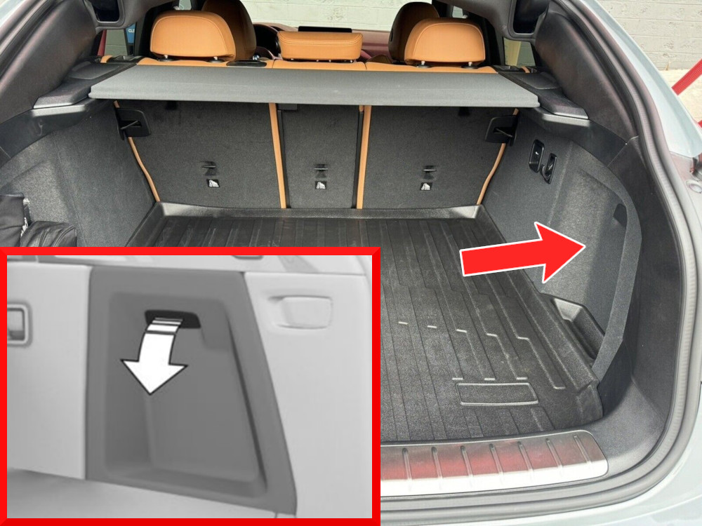
In the luggage compartment, on the right side beneath the protective cover, is the main fuse and relay box.
Assignment of the fuses in the luggage compartment
Fuse Data
Full access is available to registered users — log in or register.
Log in or register
No. Amps Description 203 7.5A Fuel injection & similar electronics 204 5A Air conditioning system, Driving assistance 206 5A Driving assistance 208 5A Driving assistance 209 5A Sound system, Gear Indicator / DSC – Dynamic Stability Control / SMG – Sequential Manual Gearbox, Fuel injection & similar electronics 210 5A Steering column function control module 212 15A Head-Up Display (HUD), Infotainment 214 5A USB 215 5A Sound system, Infotainment 216 5A Infotainment 217 40A Infotainment 218 20A Audio system 220 30A Infotainment 224 30A Air suspension compressor relay, Dynamic drive system, Load level 225 20A Main headlights / Rain sensor / Light sensor / Electronic ride height control 226 30A Electric rear sunshade, Tailgate 226 40A Electric rear sunshade, Tailgate 227 30A Fuel injection & similar electronics 230 30A Seatbelts 231 30A Rear window defroster (defogger) 240 20A Trailer module 244 5A Car alarm, Fuel pump relay / Fuel pump control, Door module / Automatic soft-close 254 5A Tailgate 255 5A Driving assistance 257 5A Seatbelts 259 15A Fuel injection & similar electronics 262 5A Air conditioning system 263 7.5A USB 264 10A Tailgate 267 30A Heated seats 269 30A Gear Indicator / DSC – Dynamic Stability Control / SMG – Sequential Manual Gearbox 271 30A Fuel pump relay / Fuel pump control, Fuel injection & similar electronics 273 20A Front & rear cigarette lighter, 12V socket / Glove box charging socket (12V) 279 5A Tailgate 282 20A Trailer module 284 20A Front & rear cigarette lighter, 12V socket / Glove box charging socket (12V), Trailer module 289 20A Trailer module 295 30A Front & rear cigarette lighter, 12V socket / Glove box charging socket (12V), Trailer module 296 20A Trailer module
This content requires JavaScript and a valid membership to view.