Explore Dodge Dakota fuse box diagrams in this straightforward guide that highlights the electrical layout of the early second-generation trucks. Here we focus on the pre-facelift Dodge Dakota (1996–2000) and provide fuse diagrams for 1997, 1998, 1999 and 2000 , along with the location of the fuse panels and the assignment of each fuse and relay , giving you a clear, useful reference for maintenance and troubleshooting.
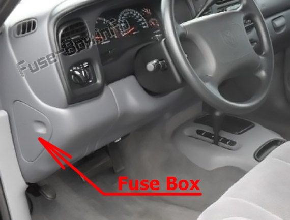
The fuse panel is located behind the cover on the driver’s side of the dashboard.
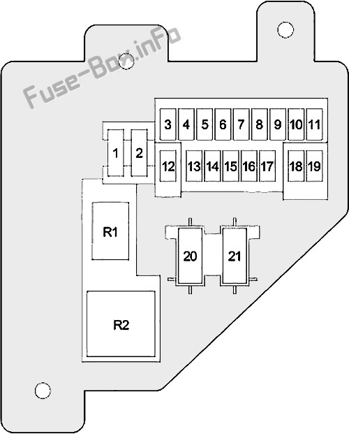
Assignment of fuses in the passenger compartment
Fuse Data
Full access is available to registered users — log in or register.
Log in or register
No. Amps Description 1 20A Headlamp Flasher Relay, Air Conditioner Compressor Clutch Relay, Horn Relay, Central Timer Module (VTSS) 2 15A Park/Neutral Position Switch (Automatic Transmission), Back-Up Lamp Switch (Manual Transmission) 3 10A ABS 4 15A Instrument Cluster 5 5A A/C Heater Control, Heater Control (except A/C), Ash Receiver Lamp, Radio, Instrument Cluster 6 20A Wiper Relay, Multi-Function Switch, Central Timer Module, Wiper Motor 7 15A Blower Motor Relay, Air Conditioner Compressor Clutch Relay 8 10A Radio 9 10A Gasoline: Powertrain Control Module, Fuel Pump Relay, Automatic Shut Down Relay, Radiator Fan Relay; 10 15A Combination Flasher 11 10A EVAP/Purge Solenoid, Overhead Console, Central Timer Module 12 15A Glove Box Lamp, Radio, Data Link Connector, Underhood Lamp/Switch, Dome Lamp, Overhead Console, Power Mirror Switch 13 20A Central Timer Switch, Power Window/Door Lock Switch 14 15A Headlamp Switch (City Lamp, Tail/Stop Lamp, License Lamp, A/C Heater Control, Heater Control (except A/C), Ash Receiver Lamp, Radio, Instrument Cluster) 15 15A Cigar Lighter 16 – Not Used 17 10A Instrument Cluster 18 10A Airbag Control Module 19 10A Airbag Control Module, Passenger Airbag On/Off Switch
This content requires JavaScript and a valid membership to view.
Assignment of circuit breakers in the passenger compartment
Fuse Data
Full access is available to registered users — log in or register.
Log in or register
No. Amps Description 20 25A Power Window/Door Lock Switch 21 – Not Used
This content requires JavaScript and a valid membership to view.
Assignment of relays in the passenger compartment
Fuse Data
Full access is available to registered users — log in or register.
Log in or register
No. Description R1 Horn R2 Combination Flasher
This content requires JavaScript and a valid membership to view.
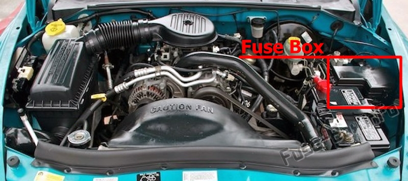
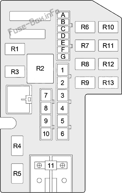
Assignment of fuses in the engine compartment
Fuse Data
Full access is available to registered users — log in or register.
Log in or register
No. Amps Description A 15A or 25A Gasoline (15A): Oxygen Sensor; B 15A Left Headlamp C 20A Fog Lamp Relay D 25A Combination Flasher E 20A Stop Lamp Switch F 10A or 20A Gasoline (20A): Transmission Control Relay; G 15A Right Headlamp 1 20A or 50A Gasoline (20A): Powertrain Control Module, Fuel Pump Relay; 2 20A or 30A Gasoline (30A): Radiator Fan Relay; 3 50A Gasoline (30A): Automatic Shut Down Relay (Fuel Injector, Ignition Coil, Powertrain Control Module, Fuse: “A”); 4 20A or 50A Gasoline (20A): Power Outlet; 5 40A Blower Motor Relay 6 50A Glow Plug Relay (Diesel) 7 50A Passenger Compartment Fuses: “1”, “4”, “12”, “13”, “14”, “21” 8 30A ABS 9 40A Starter Relay, Ignition Switch (Passenger Compartment Fuses: “2”,”3″, “7”, “18”, “20”), Radiator Fan Relay, Fuel Pump Relay, Automatic Shut Down Relay 10 40A Ignition Switch (Starter Relay, Passenger Compartment Fuses: “6”, “8”, “9”, “10”, “11”, “15”, “16”, “17”, “19”) 11 140A Generator
This content requires JavaScript and a valid membership to view.
Assignment of relays in the engine compartment
Fuse Data
Full access is available to registered users — log in or register.
Log in or register
No. Description R1 Wiper R2 Blower Motor R3 Starter R4 Not Used R5 Fog Lamp R6 Not Used R7 Transmission Control (Gasoline) R8 Air Conditioner Compressor Clutch R9 Automatic Shut Down R10 Not Used R11 Radiator Fan (Gasoline) R12 Headlamp Flasher R13 Fuel Pump (Gasoline)
This content requires JavaScript and a valid membership to view.
")
")