Browse Lincoln Aviator fuse box diagrams for 2003–2005 models with relay assignments, fuse locations, panel placement, and electrical layout information. This article covers the first-generation Lincoln Aviator (Model Code: UN152) , available from 2003 , and includes fuse box diagrams for Lincoln Aviator 2003, 2004 and 2005 , along with details about the location of the fuse panels inside the vehicle and a clear explanation of the assignment of each fuse and relay (fuse layout).
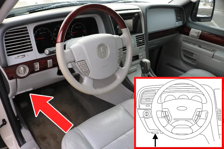
The fuse panel is located beneath the instrument panel, to the left of the steering column.
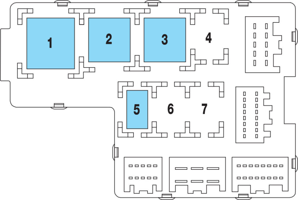
The relays are mounted on the reverse side of the passenger compartment fuse panel. To access the relays, the fuse panel must first be removed.
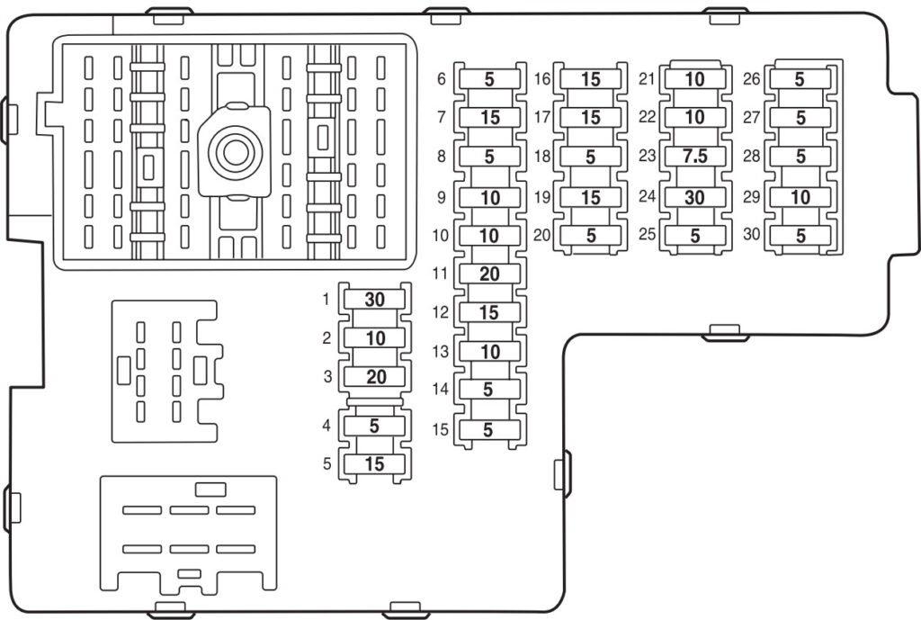
Assignment of the fuses in the passenger compartment main fuse box
Fuse Data
Full access is available to registered users — log in or register.
Log in or register
No. Amps Description 1 30A Moonroof motor, Driver seat lumbar switch 2 10A 2003: VAPS module, Memory seat module, Body security module, TPMS2004-2005: VAPS module, Memory seat module, Body security module, Tire Pressure Monitor System (TPMS), Sunload/Autolamp sensor (SecuriLock LED)3 20A Radio, Navigation system 4 5A Front wiper module 5 15A Flasher relay (turn/hazards) 6 5A Electronic Hidden Antenna Module (EHAM) (antenna amplifier), Radio, Moonroof motor, Driver window motor, Navigation module and microphone 7 15A Heated mirrors, DEATC module 8 5A 2003: Daytime Running Lamps (DRL) module2004-2005: Daytime Running Lamps (DRL) module, Heated PCV valve9 10A 2003: Back-up lamps (DTRS)2004-2005: Back-up lamps (DTRS), Electrochromatic mirror10 10A Heated backlight relay coil, Climate seat modules, Auxiliary A/C temperature blend/mode actuator, A/C clutch relay contact 11 20A N/A 12 15A Restraints module 13 10A Brake shift interlock 14 5A 2003: Cornering lamps2004-2005: N/A15 5A Instrument cluster, Rear wiper module, TPMS 16 2003, 2005: 15A2004: 20A2003: Cigar lighter, OBD II, Liftgate release relay coil and contacts2004: Cigar lighter, OBD II2005: OBD II17 15A Delayed accessory relay coil, Battery saver relay coil and contacts 18 5A N/A 19 15A Washer pump 20 5A Shifter, Clock, Power mirror switch, DVD 21 10A Brake pressure switch (ABS), IVD/RSC switch, Flasher relay 22 10A ABS/RSC module 23 2003: 5A2004-2005: 7.5A2003: Sunload/Autolamp sensor (SecuriLock transceiver LED)2004-2005: Liftgate release relay coil and contacts24 2003: 20A2004-2005: 30ASubwoofer, Navigation amp 25 5A 2003: Puddle lamp relay coil, Trailer tow battery charge relay coil2004-2005: Trailer tow battery charge relay coil26 5A SecuriLock transceiver 27 5A Rear park assist, VAPS module 28 5A Radio, Navigation 29 10A DTRS, Feed to Fuse 28 30 5A Instrument cluster, Compass module, Auxiliary A/C relay coil
This content requires JavaScript and a valid membership to view.
Assignment of the relays in the passenger compartment relay box
Fuse Data
Full access is available to registered users — log in or register.
Log in or register
No. Description 1 Flasher relay 2 Heated backlight relay 3 Delayed accessory relay 4 N/A 5 Battery saver relay 6 N/A 7 N/A
This content requires JavaScript and a valid membership to view.
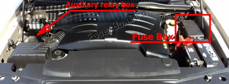
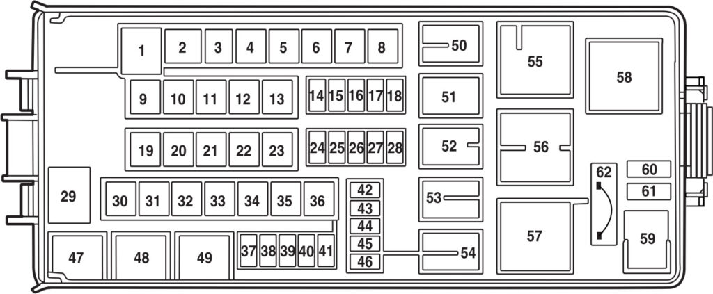
There is two fuse boxes in the engine compartment.
Assignment of the fuses and circuit breakers in the engine compartment main fuse box
Fuse Data
Full access is available to registered users — log in or register.
Log in or register
No. Amps Description 1 60A Power Junction Box (PJB) 2 30A Door locks (BSM) 3 20A 2003-2004: N/A2005: Cigar lighter4 40A Heated backlight/mirrors 5 40A Anti-lock Brake System (ABS)/Roll Stability Control (RSC) module (pump) 6 60A Delayed accessory 7 20A Daytime Running Lamps (DRL) module 8 20A Electric cooling fan 9 20A Headlamp switch 10 30A ABS/RSC module (valves) 11 40A PTEC relay contacts 12 50A Ignition/Starter relay 13 40A Trailer tow relays 14 15A Brake lamp feed 15 10A Keep alive power (PTEC/cluster/DEATC), Courtesy lights 16 20A Power point #3 17 20A Rear wiper module 18 20A 4×4 module 19 30A Driver window motor 20 30A Electric trailer brake module 21 30A Memory seat module 22 20A Main exterior lamps (low beam headlamps, high beam headlamps, fog lamps) 23 30A Ignition switch 24 20A Horn relay 25 20A Power point #1 26 20A Fuel pump relay contacts 27 20A Trailer tow lamps 28 20A Power point #2 29 60A PJB 30 30A Front wiper module 31 30A Climate-controlled seats modules 32 30A Passenger seat switch 33 30A Auxiliary blower motor 34 20A Right HID relay 35 20A Left HID relay 36 40A Blower motor 37 15A A/C clutch relay, TXV, Transmission, Speed control 38 15A 2003: HEGO, VMV, Canister vent, IMCC-LSRC, Heated PCV, EGR module2004-2005: HEGO, VMV, Canister vent, IMCC-LSRC, EGR module39 15A 2003-2004: Injectors2005: Injectors, Idle air control40 15A PTEC, Mass Air Flow (MAF) sensor, Fuel pump relay 41 25A Coil on plug, PTEC diode/relay 42 10A Right low beam (halogen) 43 10A Left low beam (halogen) 44 2003: 15A2004-2005: 2A2003: Fog lamp relay2004-2005: Heated PCV valve (w/DRL only)45 2A 2003-2004: Brake Pressure Switch2005: N/A46 20A 2003: High beam2004-2005: High beams/Fog lamps62 Circuit Breaker: 30A2003-2004: Power windows2005: Power windows, Moonroof, Audio (delayed accessory)
This content requires JavaScript and a valid membership to view.
Assignment of the relays and diodes in the engine compartment main fuse box
Fuse Data
Full access is available to registered users — log in or register.
Log in or register
No. Type Description 47 Relay Horn relay 48 Relay Fuel pump relay 49 Relay High beam relay 50 Relay Fog lamp relay 51 Relay N/A 52 Relay A/C clutch relay 53 Relay Trailer tow right turn relay 54 Relay Trailer tow left turn relay 55 Relay Blower motor relay 56 Relay Starter motor relay 57 Relay PTEC relay 58 Relay Ignition relay 59 Relay 2003-2004: Driver brake applied relay2005: N/A60 Diode PCM diode 61 Diode A/C clutch diode
This content requires JavaScript and a valid membership to view.
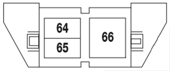
Assignment of the relays in the engine compartment auxiliary relay box (2003)
Fuse Data
Full access is available to registered users — log in or register.
Log in or register
No. Description 64 Right HID relay 65 Left HID relay 66 EDF relay
This content requires JavaScript and a valid membership to view.
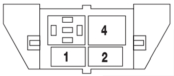
Assignment of the relays in the engine compartment auxiliary relay box (2004-2005)
Fuse Data
Full access is available to registered users — log in or register.
Log in or register
No. Description 1 Left HID relay (1/2 ISO) 2 Right HID relay (1/2 ISO) 3 Open 4 EDF relay (Full ISO)
This content requires JavaScript and a valid membership to view.
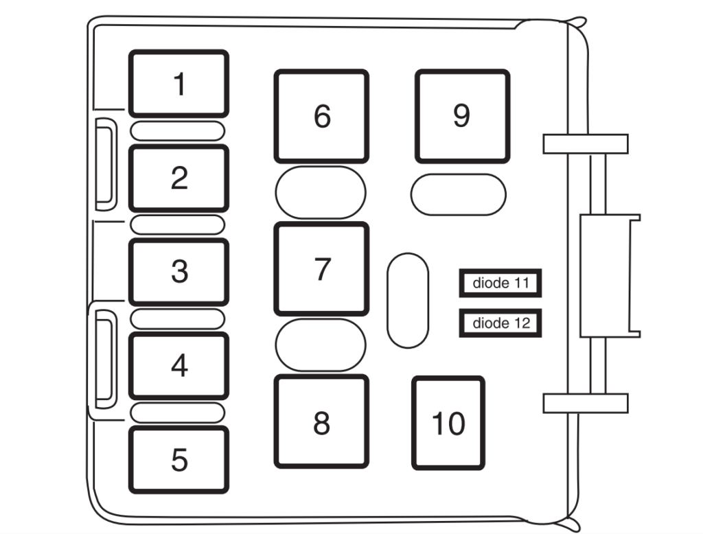
The relay box is located behind the rear passenger-side quarter trim panel.
For servicing of this relay box, contact your dealer or a certified technician.
Assignment of the relays and diodes in the rear passenger compartment relay box
Fuse Data
Full access is available to registered users — log in or register.
Log in or register
No. Type Description 1 Relay Liftgate release solenoid 2 Relay N/A 3 Relay N/A 4 Relay Trailer tow back-up lamps 5 Relay N/A 6 Relay N/A 7 Relay Trailer tow battery charge 8 Relay Trailer tow park lamps 9 Relay N/A 10 Relay 2003: Puddle lamps2004-2005: N/A11 Diode N/A 12 Diode N/A
This content requires JavaScript and a valid membership to view.
 | 2020-2024")
 | 2025-2026")