View Lincoln Aviator fuse box diagrams for 2025–2026 models with relay assignments, fuse locations, panel diagrams, and electrical system information. This article covers the facelifted second-generation Lincoln Aviator (Model Code: U611) , available from 2025 , and includes fuse box diagrams for Lincoln Aviator 2025 and 2026 , along with details about the location of the fuse panels inside the vehicle and a clear explanation of the assignment of each fuse and relay (fuse layout).
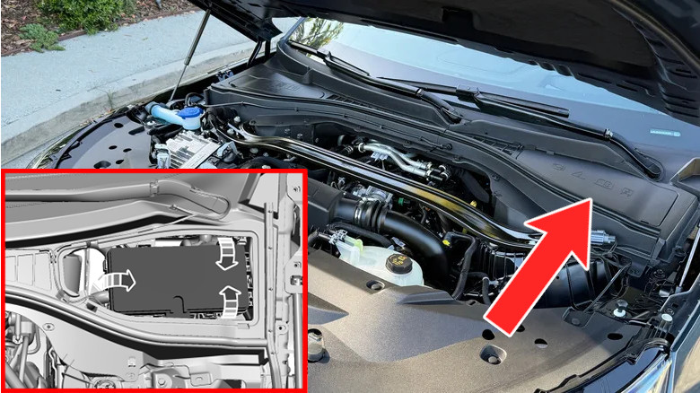
Remove the top cover to get to the fuse box and then remove the fuse box lid to access the fuses.
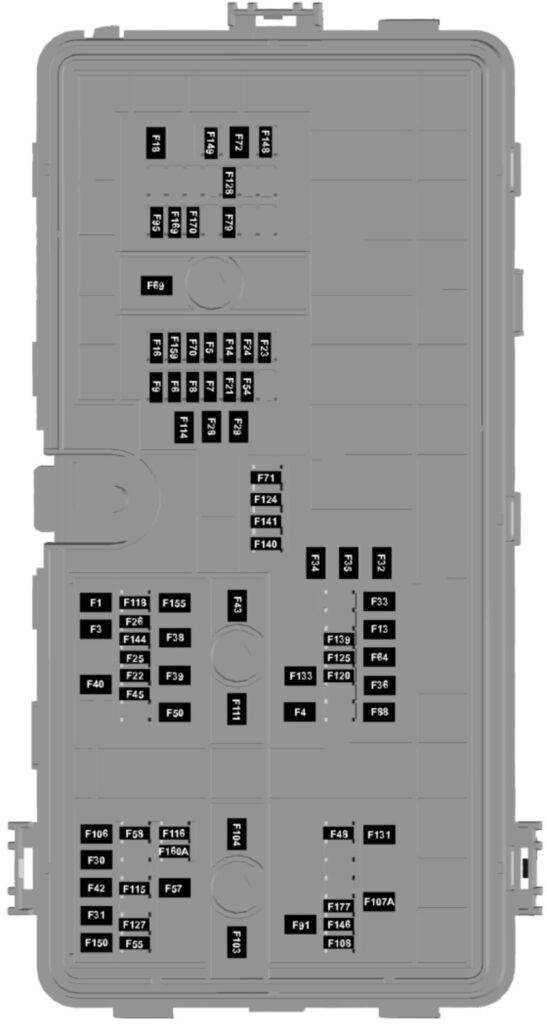
Assignment of the fuses in the engine compartment
Fuse Data
Full access is available to registered users — log in or register.
Log in or register
No. Amps Description 1 30A Body control module feed 1 3 30A Body control module feed 2 4 30A Fuel pump feed 5 5A Live power 6 20A Powertrain control module – vehicle power 1 7 20A Powertrain control module – vehicle power 2 8 20A Powertrain control module – vehicle power 3 9 20A Powertrain control module – vehicle power 4 13 40A Blower motor 14 15A Powertrain control module – aux vehicle power 3 16 15A Rear windshield washer 18 30A Starter motor solenoid 21 10A N/A 22 5A Run-start signal – electronic power assist steering 23 5A Run-start signal – anti-lock brake system 24 5A Run-start signal – powertrain control module 25 10A Air quality sensor 26 15A Run-start power – transmission oil pump 28 40A Anti-lock brake system valves 29 60A Anti-lock brake system pump 30 — N/A 31 — N/A 32 20A Power outlet 1 – front bin 33 20A Power outlet 2 – cargo area 34 20A Power outlet 3 – main bin 35 20A Power outlet 4 – back of console 36 40A 110V inverter 38 30A Climate controlled front seats (heated only seats), Climate controlled driver seats (heated/ventilated seats) 39 30A Climate controlled passenger seats (heated/ventilated seats) 40 60A Audio amplifier – 28 speaker system 42 30A Trailer tow brake control 43 40A Body control module feed 3 45 15A Run-start power – interior power distribution box 48 — N/A 50 40A Heated rear window 54 20A Run-start power – heated steering wheel 55 20A Trailer tow park lamps 57 30A Trailer tow battery charge 58 10A Trailer tow back up lamps 64 40A Driveline control module 69 30A Front wiper motor 70 10A Onboard diagnostics connector 71 15A Rear wiper motor 72 20A Air suspension valves 79 5A LED headlamp control module 88 20A Rear blower motor 91 20A Trailer tow lighting module 95 — N/A 103 — N/A 104 — N/A 106 — N/A 107 — N/A 108 — N/A 111 30A Body control module feed 4 114 50A Air suspension pump 115 20A Audio amplifier power feed 1 – 10/14 speaker system 116 — N/A 118 30A Rear heated seats 120 15A Fuel injectors 124 5A Rain sensors 125 5A USB power outlet – second row console 127 20A Audio amplifier power feed 2 – 10/14 speaker system 128 5A Lincoln star illumination 131 40A Power folding seats 133 15A Heated wiper blades 139 5A USB power outlet – back of console 140 5A USB power outlet – main bin 141 5A USB power outlet – third row 144 15A N/A 146 — N/A 148 30A Left LED headlamp 149 30A Right LED headlamp 150 — N/A 155 — N/A 159 — N/A 160 — N/A 169 — N/A 170 — N/A 177 10A Center console blower motor
This content requires JavaScript and a valid membership to view.
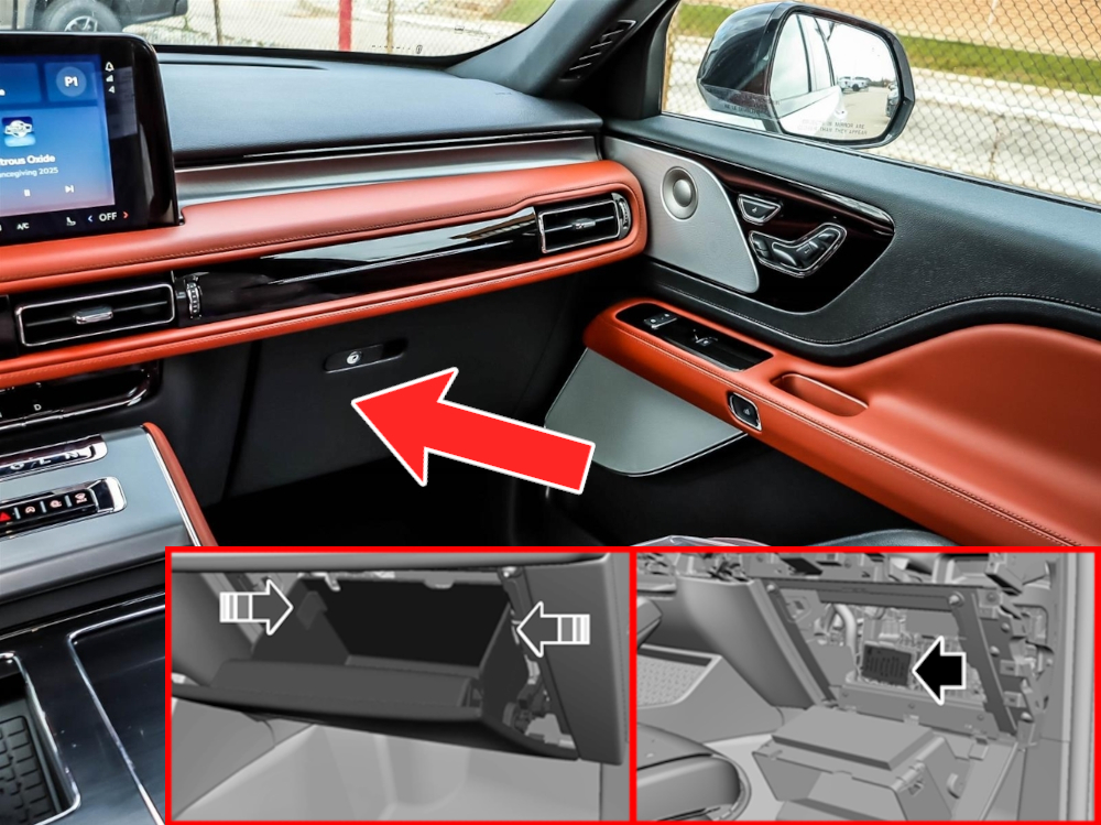
The fuse box is located behind the glove box. Refer to the image instructions for the correct procedure to access the fuse box.
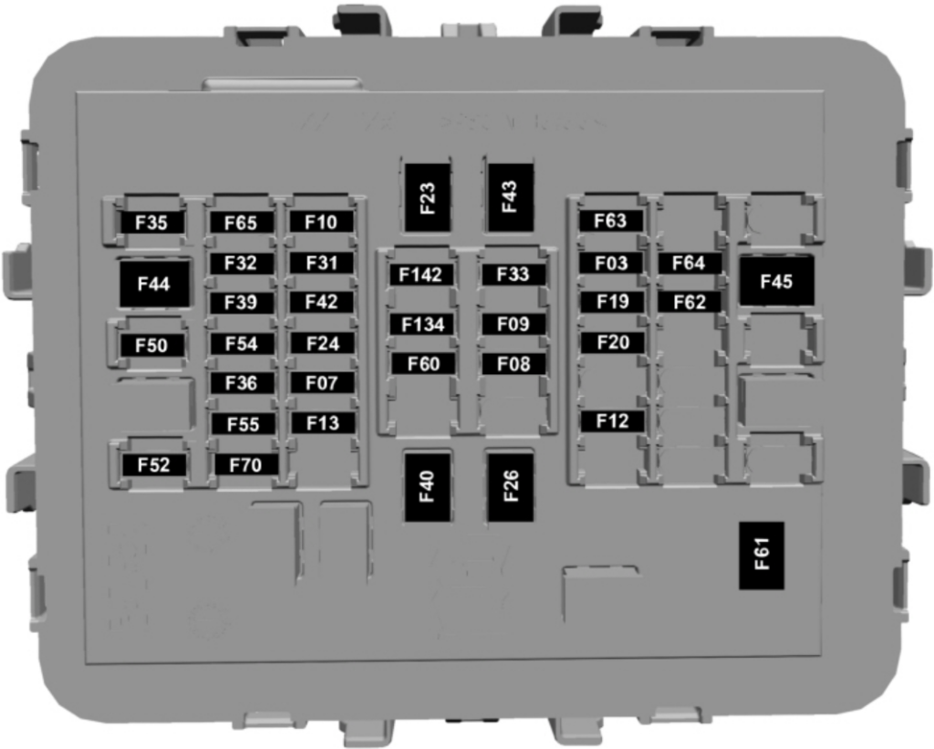
Assignment of the fuses in the passenger compartment
Fuse Data
Full access is available to registered users — log in or register.
Log in or register
No. Amps Description 3 7.5A Wireless accessory charging module, Driver seat switch, Passenger seat switch 7 7.5A Gear shift module 8 7.5A Embedded modem 9 5A Driver keypad, Passenger keypad, Rear audio control module 10 15A Driver multi-contour seat module, Passenger multi-contour seat module 12 5A Climate control module 13 7.5A Steering column control module 19 7.5A Head up display module, Bluetooth low energy module 20 5A Headlamp switch 23 60A Driver door module 24 30A Glass roof 26 60A Passenger door module 31 10A Terrain management switch, Enhanced central gateway, Radio transceiver module 32 20A Radio 33 7.5A Instrument cluster 35 15A Center display 36 5A N/A 39 5A Power liftgate module, Driver status monitor camera 40 60A N/A 42 15A Phoenix module, Integrated control panel 43 30A Power liftgate module 44 30A Driver seat motors 45 30A Passenger seat motors 50 10A Continuous control dampening 52 5A All wheel drive module 55 5A Auto dimming rear view mirror 60 10A Glass roof, Power inverter 61 30A N/A 62 20A Driver door E-latch 63 20A Passenger door E-latch 64 20A Passenger rear door E-latch 65 20A Driver rear door E-latch 70 20A Advanced driver assistance system 134 10A N/A 142 5A N/A
This content requires JavaScript and a valid membership to view.
 | 2003-2005")
 | 2020-2024")