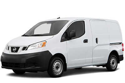
Browse Nissan NV200 fuse box diagrams for 2013–2021 models with fuse locations, panel layouts, and detailed fuse and relay assignment information for this compact commercial van. This article covers the Nissan NV200 (Model Code: M20), available from 2013 to 2021 , and includes fuse box diagrams for Nissan NV200 2013, 2014, 2015, 2016, 2017, 2018, 2019, 2020 and 2021 , along with details about the location of the fuse panels inside the vehicle and a clear explanation of the assignment of each fuse and relay (fuse layout).
NEED A REPLACEMENT?
Looking for the right fuse or relay?
Search common fuse types, fuse kits and relay options for your vehicle.
Find Fuses & Relays
→
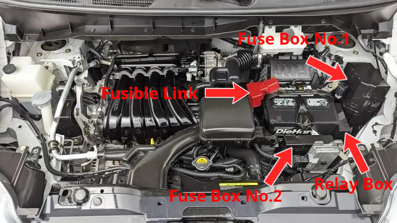
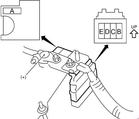
There are several fuse boxes in the engine compartment, all positioned around the main battery. The fusible link is mounted directly on the battery’s positive terminal. Refer to the image below to locate each fuse box.
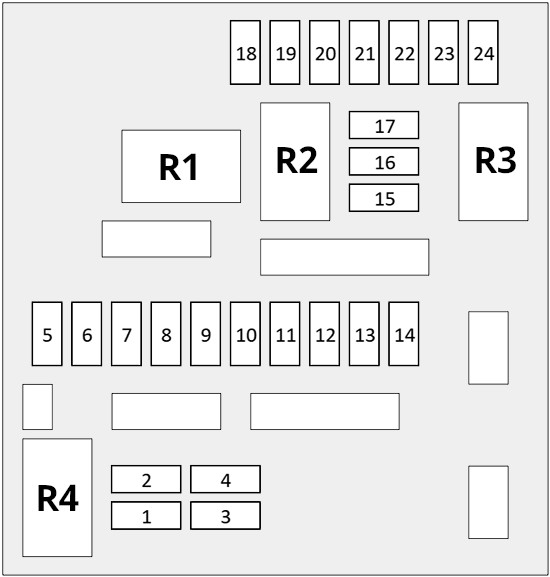
Assignment of the fuses in the engine compartment fuse box No.1
Fuse Data
Full access is available to registered users — log in or register.
Log in or register
No. Amps Short-Code Description 1 20A RR DEF Rear window defogger 3 20A VCM ECM relay 4 10A ESCL ESCL 5 30A FR WIPER Front wiper 6 10A POS LAMP R Parking, license plate and tail lamps 7 10A POS LAMP L Parking, license plate and tail lamps 9 10A A/C A/C compressor clutch 10 15A FR FOG LAMP Front fog lamp 11 10A H/LAMP HI RH Headlamp (high RH) 12 10A H/LAMP HI LH Headlamp (high LH) 13 15A H/LAMP LO RH Headlamp (low LH) 14 15A H/LAMP LO LH Headlamp (low RH) 15 10A VCM IGN A/T control system 16 10A REV LAMP IGN Reversing lamp 17 10A ABS ECU IGN ABS control 20 15A FUEL PUMP Fuel pump 21 15A PBW/VDC IGN Ignition system 22 15A E-ACT/HAS IGN Fuel injector 24 15A F/S1 RLY Throttle control motor 15A ETC Accessories, Power steering
This content requires JavaScript and a valid membership to view.
Assignment of the relays in the engine compartment fuse box No.1
Fuse Data
Full access is available to registered users — log in or register.
Log in or register
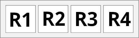
No. Description R1 Cooling fan relay – 1 R2 Cooling fan relay – 2 R3 Ignition relay R4 Rear window defogger relay
This content requires JavaScript and a valid membership to view.
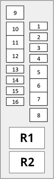
Assignment of the fuses in the engine compartment fuse box No.2
Fuse Data
Full access is available to registered users — log in or register.
Log in or register
No. Amps Short-Code Description 2 10A DTRL Daytime running lights 3 10A ALT-S Charging system 4 10A HORN Horn relay 5 60A EPS Electronically controlled power steering control unit 6 30A H/LAMP WASHER Headlight washers 7 30A ABS ABS solenoid 8 40A P/WDW BCM Windows, body electronics module (BCM) 9 40A ABS MTR ABS motor 40A PTC/ROOF Auxiliary heater 10 40A IGN SW Starting system 11 40A RAD FAN Engine cooling fan system 12 40A RAD FAN Engine cooling fan system 40A ABS ABS, ESP 13 15A AUDIO Audio 14 10A CVT CVT system
This content requires JavaScript and a valid membership to view.
Assignment of the relays in the engine compartment fuse box No.2
Fuse Data
Full access is available to registered users — log in or register.
Log in or register
No. Description R1 Horn Relay R2 Daytime Running Lights Relay
This content requires JavaScript and a valid membership to view.
Assignment of the high-voltage fuses in the engine compartment fusible link
Fuse Data
Full access is available to registered users — log in or register.
Log in or register
No. Amps Description A 80A/140A/250A Charging system, starting system, fuses B 80A/100A Fuses C 80A Fuses D 60A Ignition relay, fuses, fuel pump relay E 80A Auxiliary relay, fuses, heater relay
This content requires JavaScript and a valid membership to view.
Assignment of the relays in the engine compartment relay box
Fuse Data
Full access is available to registered users — log in or register.
Log in or register
No. Description R1 (DTRL) Daytime light relay 2 R2 (DTRL) Daytime light relay 1 R3 (RAD FAN HI) Engine cooling fan system (HI) R4 (RAD FAN LO) Engine cooling fan system (LO)
This content requires JavaScript and a valid membership to view.
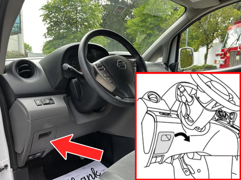
The fuse box is located on the driver’s side, to the left of the steering wheel beneath the cover. Pull off the cover to access the fuses.
Assignment of the fuses in the passenger compartment fuse box
Fuse Data
Full access is available to registered users — log in or register.
Log in or register
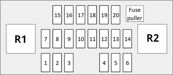
No. Amps Short-Code Description 1 15A BLOWER AC blower motor 2 15A BLOWER AC blower motor 10A AIR COND Air conditioning 3 10A AIR COND Air conditioning 15A BLOWER AC blower motor 4 20A FR POWER OUTLET Front power outlet 5 20A RR POWER Rear power outlet 15A CIGAR LIGHTER Cigar lighter / power outlet 7 10A STOP LAMP Stop lights 10 10A ELEC PARTS1 Protects several circuits 11 10A STOP LAMP Brake lights, ABS, ESP, warning indicators 12 10A PASSIVE ENTRY PASSIVE ENTRY 13 10A ELEC PARTS2 Protects several circuits 14 10A ELEC PARTS1 Protects several circuits 15 10A ELEC IG Protects several circuits 16 10A AIR BAG Airbag 17 10A METER Instrument cluster 18 10A WASHER MOTOR Windshield washer 19 10A AUDIO / MIRROR AUDIO MIRROR 20 10A HEATER MIRROR Mirror heater
This content requires JavaScript and a valid membership to view.
Assignment of the relays in the passenger compartment fuse box
Fuse Data
Full access is available to registered users — log in or register.
Log in or register
No. Description R1 Heater fan relay R2 Interior auxiliary equipment relay
This content requires JavaScript and a valid membership to view.