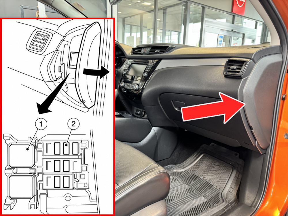
Explore Nissan Qashqai (Rogue Sport) fuse box diagrams for 2014–2022 models with fuse locations, panel layouts, and detailed fuse and relay assignments. This article covers the second-generation Nissan Qashqai (Model Code: J11), also sold as the Nissan Rogue Sport in the United States, available from 2014 to 2022, and includes fuse box diagrams for Nissan Qashqai (Rogue Sport) 2014, 2015, 2016, 2017, 2018, 2019, 2020, 2021 and 2022, along with details about the location of the fuse panels inside the vehicle and a clear explanation of the assignment of each fuse and relay (fuse layout).
NEED A REPLACEMENT?
Looking for the right fuse or relay?
Search common fuse types, fuse kits and relay options for your vehicle.
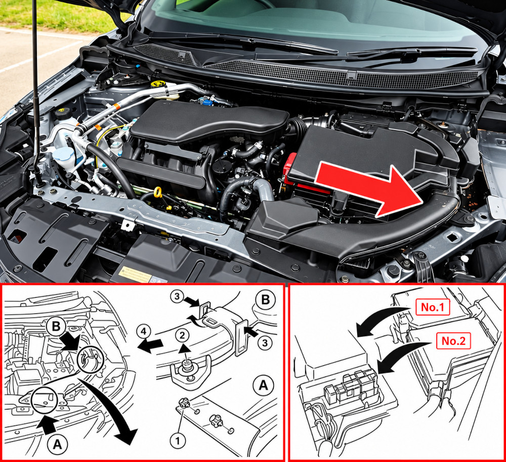
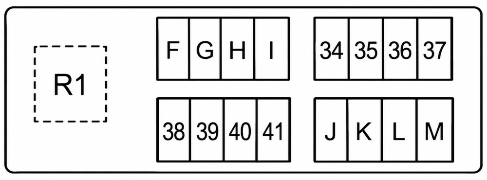
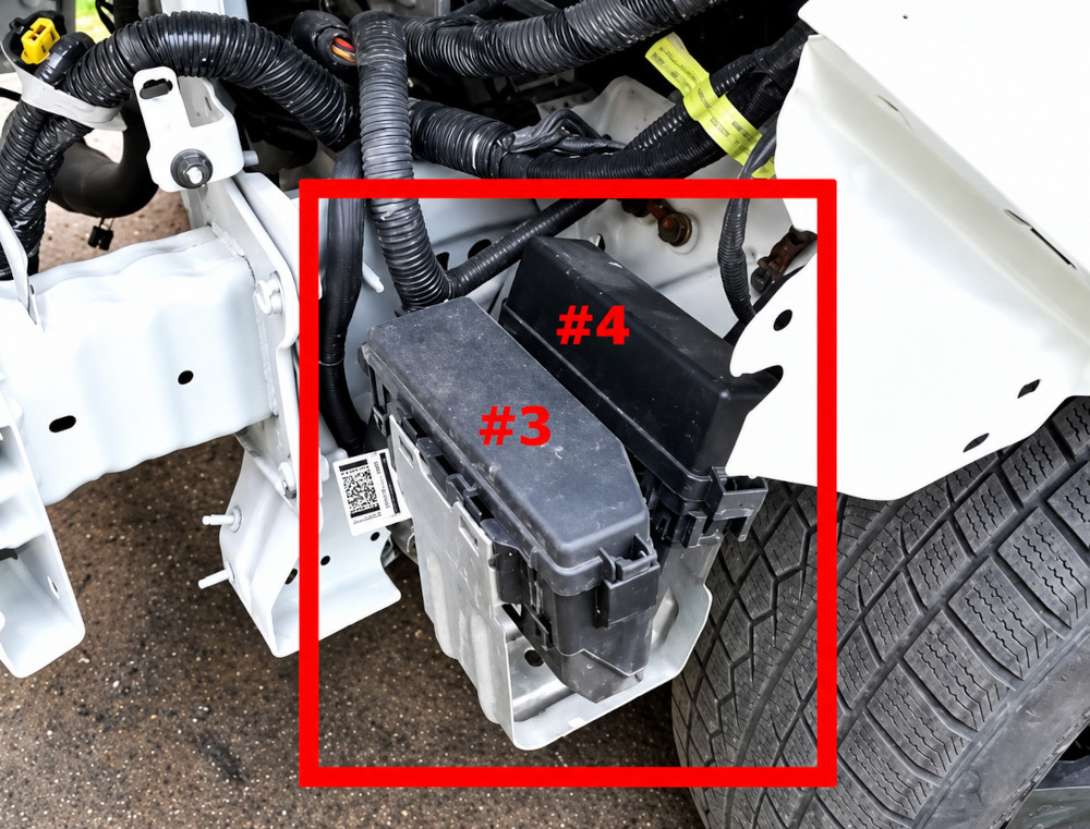
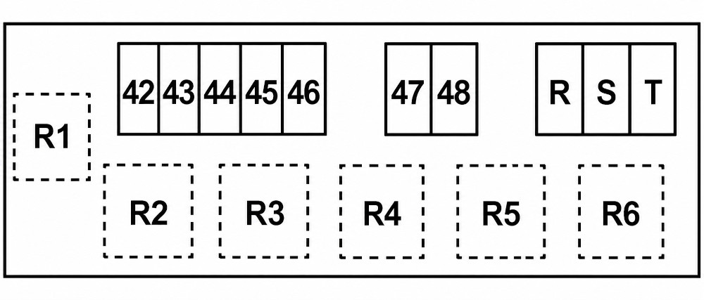
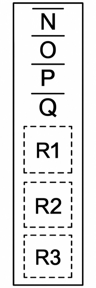
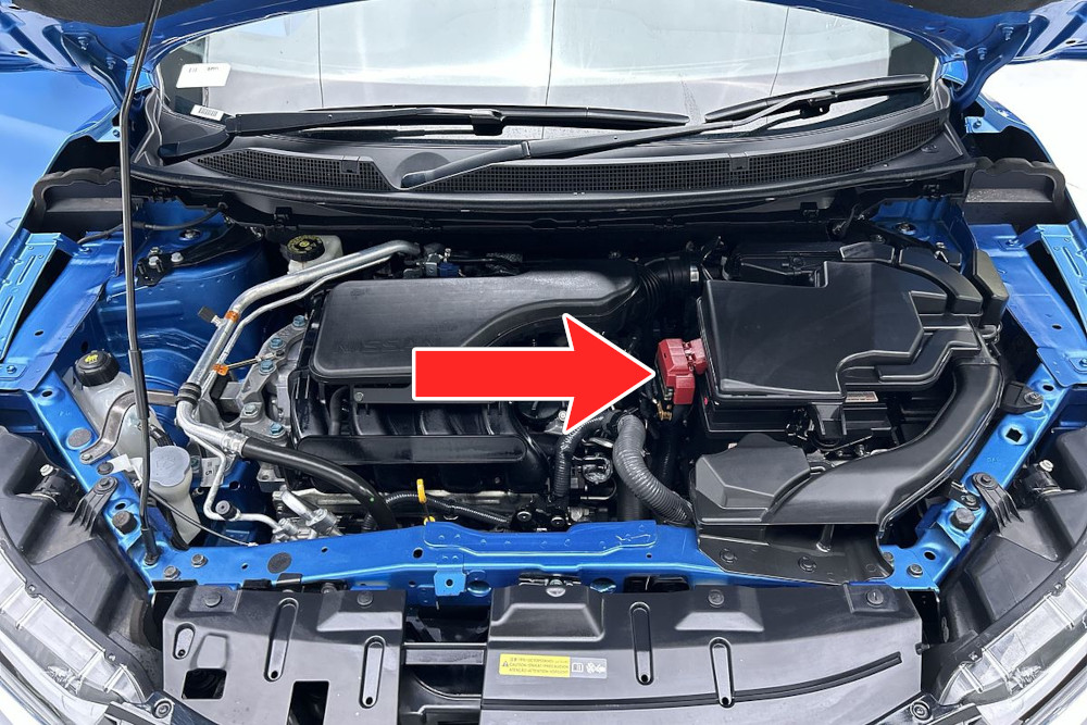
There are two fuse boxes beneath the air duct near the main battery in the engine compartment. To access the fuses: (1) Remove the clips, (2) remove the bolt, (3) press the tops of the retaining clips together to release the air duct, and (4) slide the air duct toward the front of the vehicle to remove it.
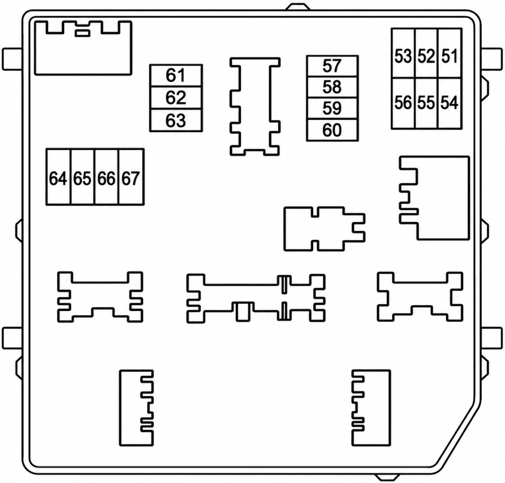
Fuse Box Diagram (No.1)
Fuses
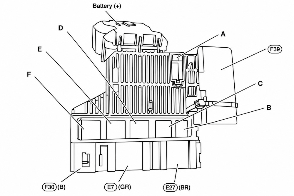
Assignment of the fuses in the engine compartment fuse box No.1
Fuse Data
Full access is available to registered users — log in or register.
Engine Control Module, EVAP Canister Purge Volume Control Solenoid Valve, Engine Coolant Bypass Valve Control Solenoid Valve, Fuel Heater and Water in Fuel Level Sensor, High Pressure Fuel Pump, Condenser, Ignition Coils, Exhaust Valve Timing Control Solenoid Valve, Intake Valve Timing Control Solenoid Valve, Fuel Injector Relay, High Pressure Fuel Pump Relay, Mass Air Flow Sensor, Heated Oxygen Sensor, Turbocharger Waste Gate Control Solenoid Valve, Air Fuel Ratio Sensor, Fuel Flow Actuator, Turbocharger Boost Control Solenoid Valve, Intake Valve Timing Intermediate Solenoid Valve, Intake Valve Timing Control Solenoid Valve, Turbocharger Bypass Control Valve, Engine Oil Pressure Control Solenoid Valve
53
15A
MR: Throttle Control Motor Relay
54
10A
Engine Control Module, Engine Coolant Bypass Valve Control Solenoid Valve, Intake Valve Timing Control Solenoid Valve, Engine Oil Pressure Control Solenoid Valve, Exhaust Valve Timing Control Solenoid Valve, Turbocharger Bypass Valve Control Solenoid Valve, Intake Manifold Runner Control Valve
55
15A
Engine Control Module, Heated Oxygen Sensor, Thermostat Heater Control Solenoid Valve, Glow Control Unit, Turbocharger Boost Control Solenoid, Air Fuel Ratio Sensor, Fuel Flow Actuator, Intake Manifold Runner Control Valve
Auxiliary relay (fuses: “13”, “14”, “15”), rear window heating relay (fuses: “10”, “11”, “12”), heater relay (fuses: “7”, “17”), front wiper relay, right headlight, rear right lamp, front right fog lamp, fuses: “19”, “20”, “21”, “22”, “24”, “25”, “26”, “27”, “28”, “29”, “30”, “31”, “32”, “33”, “57”, “58”, “U”
D
100A
Ignition relay (fuses: “56”, “61”, “63”, “65”, “67”), air conditioning relay, engine cooling fan relay 1, left headlight, rear left lamp, front left fog lamp, fuses: “P”, “Q”
E
50A
Fuses: “R”, “S”, “T”, “42”, “44”, “45”, “46”
U
100A
Right headlight, rear right lamp, front right fog lamp, glow plug control unit, thermo plunger control unit, fuse: “58”
Combination Switch, Pump Control Unit, Washer Switching Solenoid Valve
2
10A
Air Bag Diagnosis Sensor Unit
3
5A
Combination Meter
4
10A
Sonar Control Unit, PTC Relay 1, PTC Relay 2, PTC Relay 3, Front Camera Unit, Illumination, Audio, Fuel Heater Relay, Data Link Connector, Stop Lamp Switch, Distance Sensor, Auto Anti-dazzling Inside Mirror, EPS Control Unit, Combination Switch (Spiral Cable), Chassis Control Module, Auto Anti-dazzling Inside Mirror, 4WD Control Unit, Electric Park Brake Control Unit, Around View Monitor Control Unit, Steering Angle Sensor, Navi Control Unit
5
10A
DC/DC Converter
6
15A
Front Heated Seat Switch
7
20A
Blower Motor, Air Conditioner Amplifier, Engine Restart Baypass Control Relay
8
5A
Stop Lamp LH, Tail Lamp LH, License Plate Lamps, Glove Box Lamp, Headlamp Aiming Switch, Audio, Navi Control Unit
9
–
–
10
15A
Rear Window Defogger
11
15A
Rear Window Defogger
12
10A
Door Mirror Heater
13
10A
ABS
14
10A
Air Conditioner Control, Air Conditioner Amplifier, Sunshade Motor Assembly, Brake Pedal Position Switch, Stop Lamp Switch, Door Mirror Remote Control Switch
15
15A/20A
Interior Room Lamp Relay
16
–
–
17
20A
Blower Motor, Power Transistor, Air Conditioner Amplifier
18
–
–
19
20A
Audio, Navi Control Unit, Around View Monitor Control Unit
20
5A
BCM (Body Control Module), Siren Control Unit, Sensor Cancel Switch, Combination Switch
21
10A
Combination Meter
22
10A
Interior Room Lamp Relay
23
–
–
24
10A
Stop Lamp Switch, BCM (Body Control Module)
25
5A
4WD Control Unit, NATS Antenna Amplifier
26
5A
Clutch Interlock Switch
27
10A
BCM (Body Control Module), Combination Switch
28
10
Electric Park Brake Switch, Data Link Connector, 4WD Control Unit, Illumination, Power Window Relay, Door Mirror Open Relay, Door Mirror Close Relay
29
15A/20A
BCM (Body Control Module)
30
15A
BCM (Body Control Module)
31
15A/20A
BCM (Body Control Module)
32
15A/20A
Power Socket
33
10A/15A
Flashers, turn lights, direction indicators and Hazard warning lights
Relays
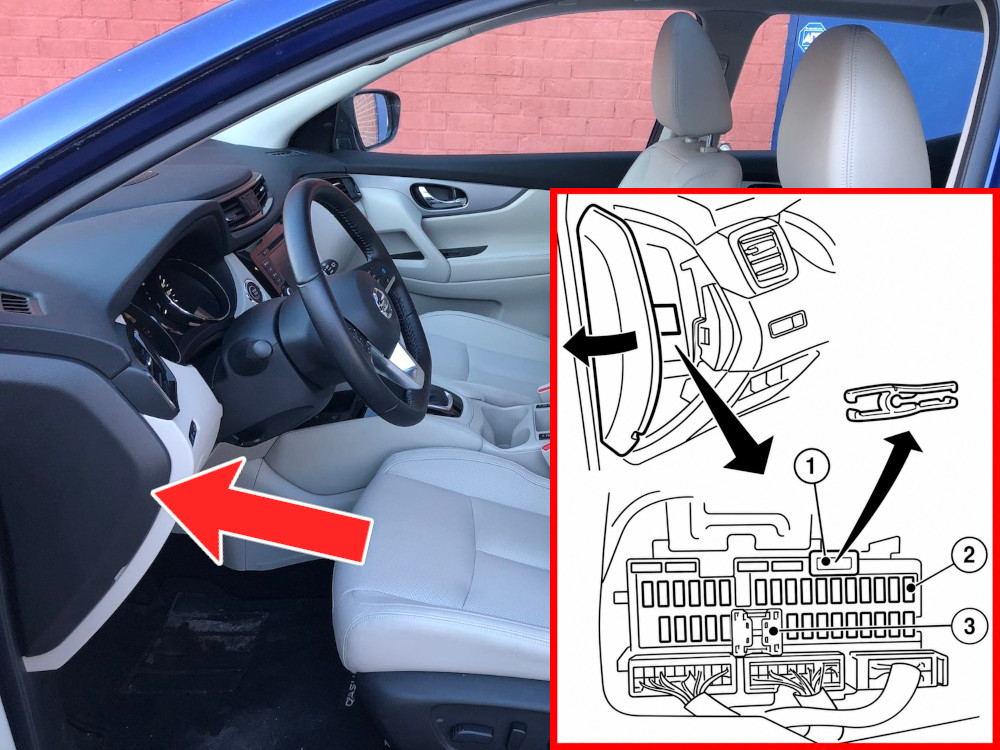
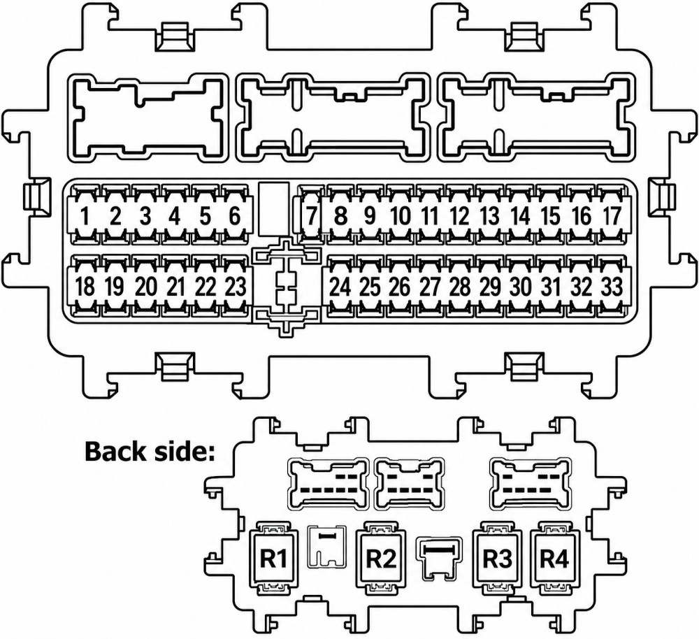
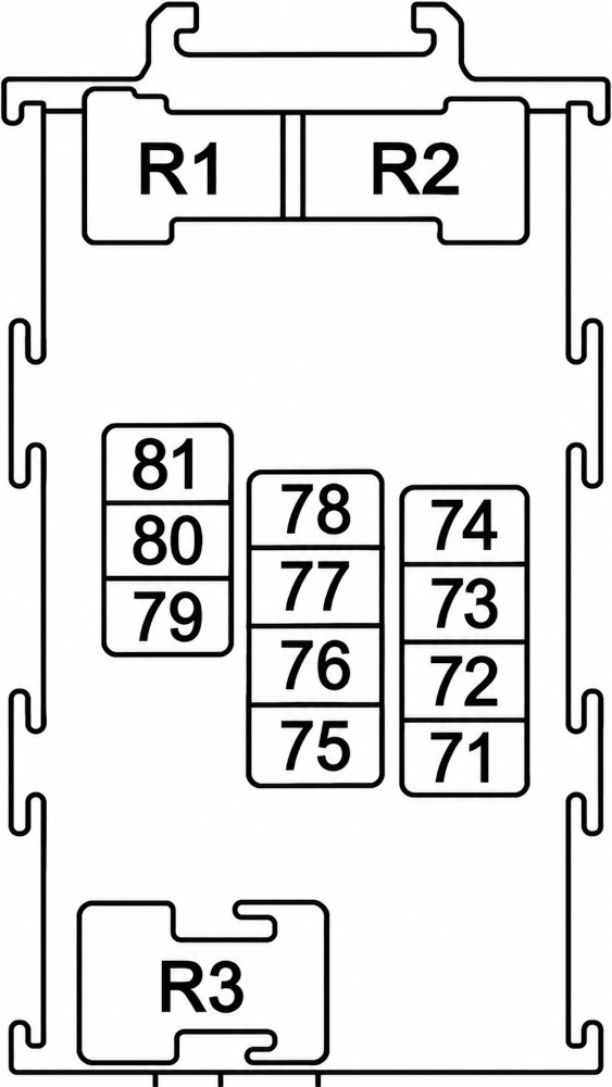
Assignment of the relays in the passenger compartment left side of the dashboard
Fuse Data
Full access is available to registered users — log in or register.