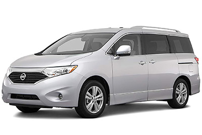
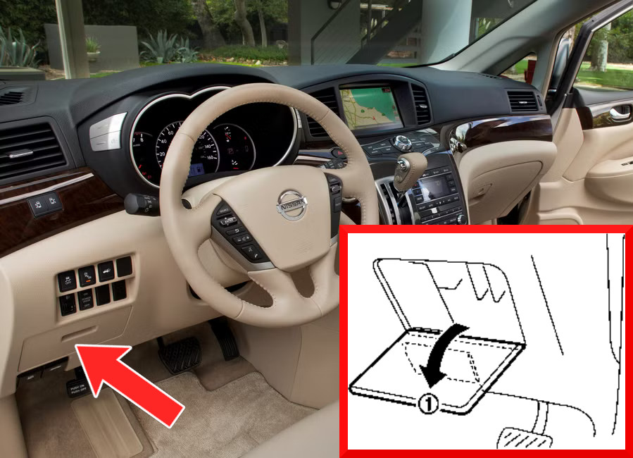
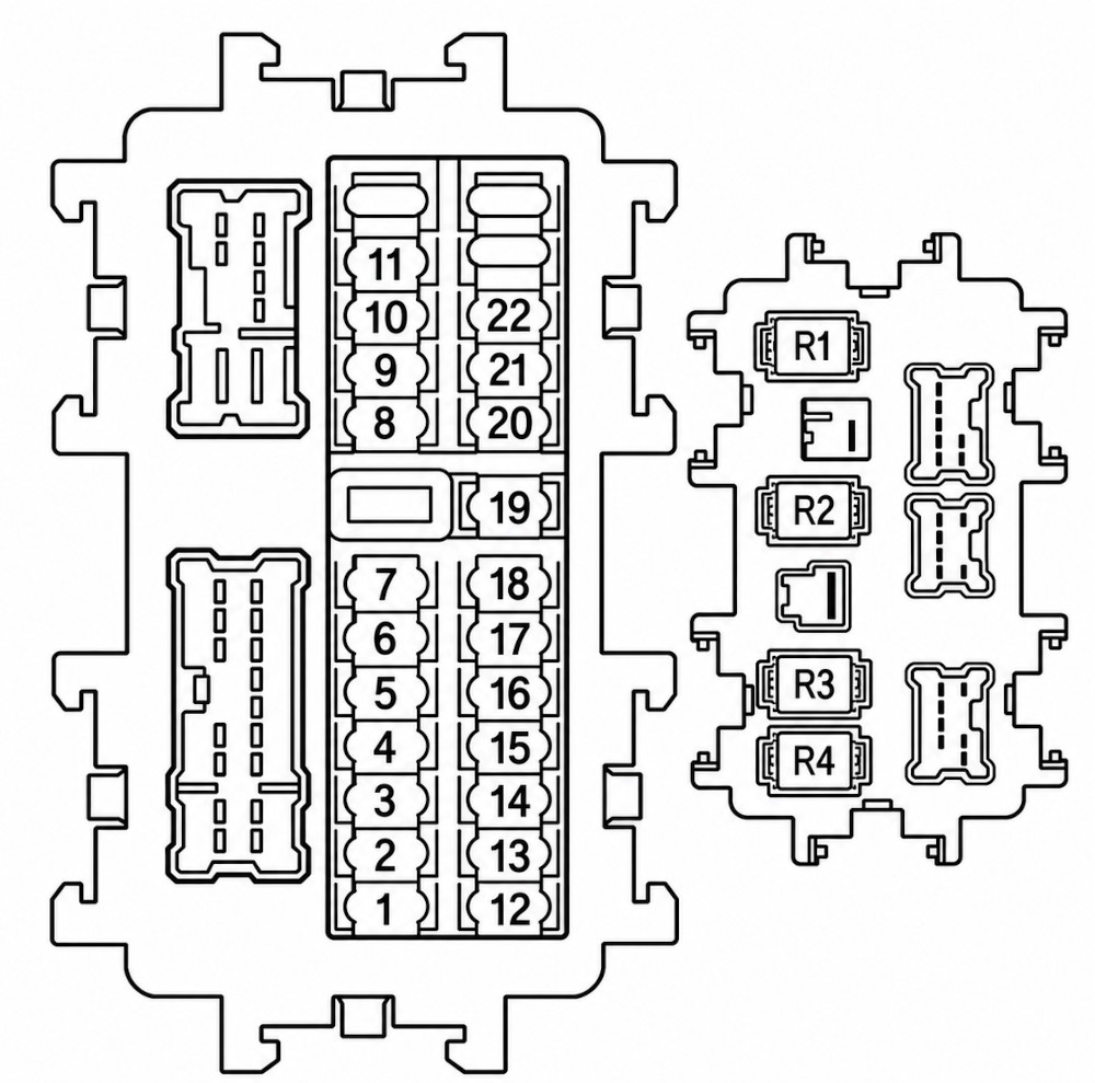
Browse Nissan Quest fuse box diagrams for 2011–2017 models with fuse locations, panel layouts, and detailed fuse and relay assignment information. This article covers the fourth-generation Nissan Quest (Model Code: RE52), available from 2011 to 2017, and includes fuse box diagrams for Nissan Quest 2011, 2012, 2013, 2014, 2015, 2016 and 2017, along with details about the location of the fuse panels inside the vehicle and a clear explanation of the assignment of each fuse and relay (fuse layout).
NEED A REPLACEMENT?
Looking for the right fuse or relay?
Search common fuse types, fuse kits and relay options for your vehicle.
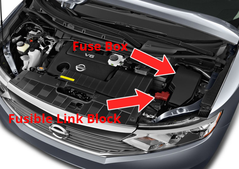
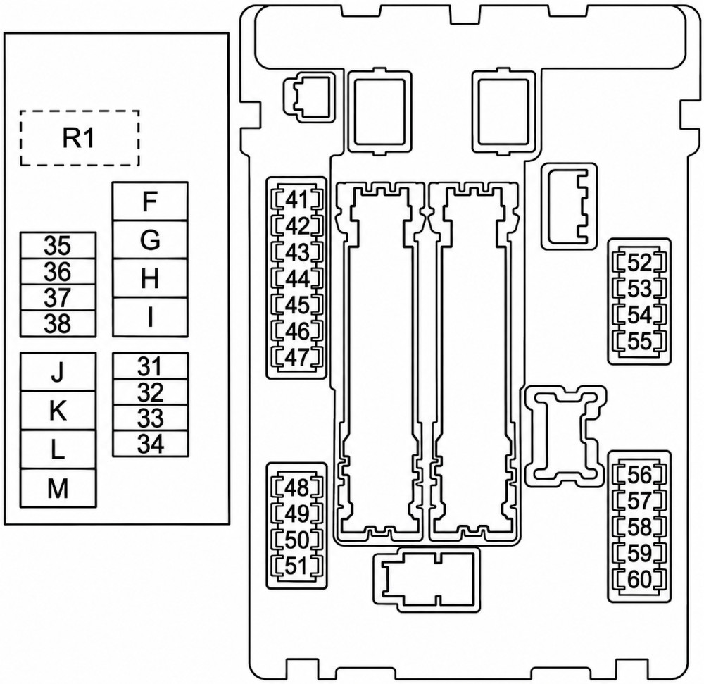
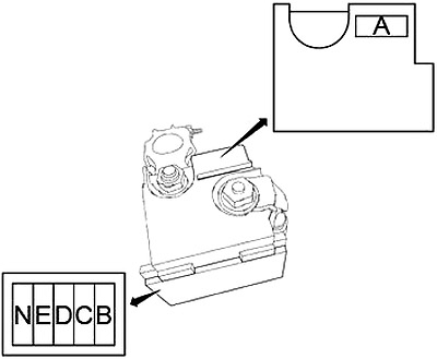
The fuse box is positioned on the driver’s side of the engine compartment, while the fusible link block is mounted on the main battery’s positive (+) terminal.
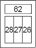
Fuse Box Diagram
Fuses
Assignment of fuses in the engine compartment fuse box
Fuse Data
Full access is available to registered users — log in or register.
Circuit Breaker (Automatic Back Door Control Module), Circuit Breaker (Sliding Door Control Unit, Back Door Control Unit)
K
40A
Cooling Fan Relay 2, Cooling Fan Relay 3
L
40A
BCM (Body Control Module), Circuit Breaker (Automatic Drive Positioner Control Unit, Driver Seat Control, Lumbar Support Switch)
M
40A
Cooling Fan Motor 1
41
15A
Fuel Pump Relay
42
10A
Cooling Fan Relay 2, Cooling Fan Relay 3
43
10A
Secondary Speed Sensor, Transmission Control Module (TCM)
44
10A
Injectors, Engine Control Module (ECM)
45
10A
ABS, BSW Switch, BSW Control Module, Side Radar
46
15A
Air Fuel Ratio Sensor, Heated Oxygen Sensor
47
10A
Combination Switch
48
–
Not Used
49
10A
Air Conditioner Relay
50
15A
Engine Control Module Relay (VIAS Control Solenoid, Intake Valve Timing Control Solenoid Valve, EVAP Canister Vent Control Valve, Condenser, Ignition Coils, Engine Control Module, Mass Air Flow Sensor, EVAP Canister Purge Volume Control Solenoid Valve)
51
15A
Throttle Control Motor Relay
52
10A
Front Combination Lamps, Front Side Marker Lamps, Headlamp Aiming
53
10A
Rear Combination Lamps, License Plate Lamps, VDC Off Switch, Headlamp Aiming Switch, Glove Box Lamp, AC 120V Outlet Main Switch, Automatic Door Main Switch, Combination Switch, Hazard Switch, Air Conditioner Amplifier, Meter Control Switch, Illumination Control Switch, BSW Switch, Automatic Back Door Switch, CVT Shift Selector Illumination, Foot Lamps, Sliding Door Open / Close Switch, Audio, Heated Seat Switch, Rear Air Conditioning Control, Map Lamp, Door Mirror Remote Control Switch, Disc Eject Switch, Multifunction Switch, Rear Display Unit
54
10A
Headlamp High (Left)
55
10A
Headlamp High (Right)
56
15A
Headlamp Low (Left)
57
15A
Headlamp Low (Right)
58
15A
Front Fog Light
59
10A
Daytime Running Light Relay
60
30A
Front Wiper Relay
Relays
Assignment of relays in the engine compartment fuse box
Fuse Data
Full access is available to registered users — log in or register.
Air Bag Diagnosis Sensor Unit, Occupant Classification System Control Unit
3
10A
Air Conditioner Amplifier, Automatic Back Door Control Module, Sliding Door Control Unit, Power Steering Control Module, ASCD Brake Switch, Stop Lamp Switch, Exhaust Gas / Outside Odor Detecting Sensor, Electronic Controlled Engine Mount Control Solenoid Valve, Data Link Connector, AC 120V Outlet Main Switch, Steering Angle Sensor, Ionizer, Tel Adapter Unit, AV Control Unit, Rear Display Unit, Auto Anti-Dazzling Inside Mirror, Around View Monitor Control Unit, Rear Air Conditioning Control
4
10A
Combination Meter, Back-Up Relay
5
—
Not Used
6
15A
Intelligent Key Warning Buzzer, Data Link Connector, Air Conditioner Amplifier, Selective Unlock Relay, Auto Anti-Dazzling Inside Mirror, Combination Meter
7
10A
Stop Lamp Switch, Stop Lamp Relay, BCM (Body Control Module)
8
20A
Luggage Room Power Socket
9
10A
Automatic Back Door Control Module, Automatic Back Door Warning Buzzer, Automatic Sliding Door Warning Buzzer, Sliding Door Control Unit, Seatback Power Return Control Unit, Seatback Lock Release Actuator Relay
Transmission Control Module (TCM), Push-Button Ignition Switch
12
—
Not Used
13
10A
Door Mirror, Air Conditioner Amplifier
14
—
Not Used
15
20A
Rear Window Defogger
16
—
Not Used
17
—
Not Used
18
—
Not Used
19
10A
Air Conditioner Amplifier, Audio, Tel Adapter Unit, Multifunction Switch, Front Display Unit, AV Control Unit, Satellite Radio Tuner, Rear Display Unit, Door Mirror Remote Control Switch
20
20A
Front Power Socket
21
15A
Front Blower Motor
22
15A
Front Blower Motor
Relays
Assignment of relays in the passenger compartment fuse box
Fuse Data
Full access is available to registered users — log in or register.