Nissan Xterra (WD22) | 1999-2004

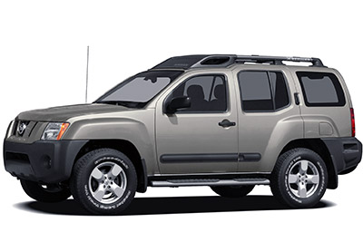
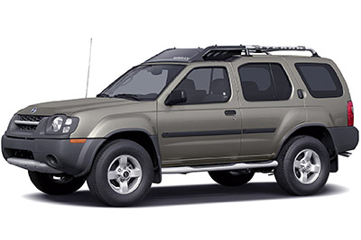
Explore Nissan Xterra fuse box diagrams for 1999–2004 models with fuse locations, panel layouts, and detailed fuse and relay assignment information. This article covers the first-generation Nissan Xterra (Model Code: WD22), available from 2000, and includes fuse box diagrams for Nissan Xterra 1999, 2000, 2001, 2002, 2003 and 2004, along with details about the location of the fuse panels inside the vehicle and a clear explanation of the assignment of each fuse and relay (fuse layout).

Engine Compartment

Fuse Box Location

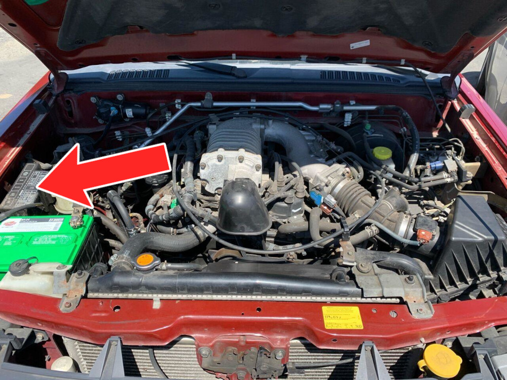
The fuse box is situated in the engine compartment on the passenger side, beside the main battery.

Fuse Box Diagram

Fuses

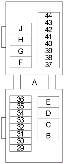
Assignment of the fuses in the engine compartment

Fuse Data
Full access is available to registered users — log in or register.
Log in or register

No.AmpsDescription
297.5AAir Conditioner Relay, Daytime Light Control Unit (2003-2004), Thermo Control Amplifier (1999-2000), Air Conditioner Switch (1999-2000)
30Not Used
317.5A / 20A1999-2000: Theft Warning Horn Relay, Theft Warning Lamp Relay (7.5A)
2003-2004: Auxiliary Power Supply (20A)
3210A / 15AHorn Relay
3320A2002-2004: Audio Amplifier
3415A2002-2004: Rear Power Socket
357.5AAir Conditioner Relay
367.5AGenerator
3715AHeadlamp RH, Lighting Switch, Daytime Light Control Unit, Vehicle Security Lamp Relay
3815AHeadlamp LH, Lighting Switch, Daytime Light Control Unit, Vehicle Security Lamp Relay, High Beam Indicator
3915ALighting Switch
4015AFront Fog Lamp Relay
4115AAudio
4220AFront Power Socket
43Not Used
44Not Used
A80A / 100A / 120AKA24DE: Generator, Ignition Relay (Fuses “2”, “5”, “6”, “8”, “10”, “11”, “12”, “15”), Fuses “F”, “G”, “17”, “22”, “25”, “26”, “27”, “28”, “31”, “32”, “33”, “34”, “35”, “36” (80A)
1999-2002 (VG33E, VG33ER): Generator, Fuses “F”, “G”, “J”, “31”, “32”, “35”, “36” (100A)
2003-2004 (VG33E, VG33ER): Generator, Fuses “F”, “G”, “J”, “31”, “32”, “33”, “34”, “35”, “36” (120A)
B80AAccessory Relay (Fuses “18”, “20”, “23”), Blower Relay (Fuses “19”, “24”)
C30A / 40AABS
D40AABS
E40AIgnition Switch
F30A / 40ASECU, Power Window Relay
G20ACooling Fan Relay
2003-2004: Auxiliary Power Supply
HNot Used
J80AVG33E, VG33ER: Ignition Relay (Fuses “2”, “5”, “6”, “8”, “10”, “11”, “12”, “15”), Fuses “31”, “32”, “33”, “35”, “36”

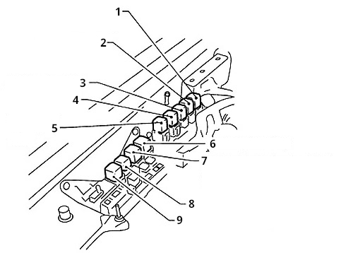
Relay Box Diagram (1999-2001)

Relays

Assignment of the relays in the engine compartment (1999-2001)

Fuse Data
Full access is available to registered users — log in or register.
Log in or register

No.Description
1Multi-Remote Control Relay
2Theft Warning Lamp Relay
3ASCD Relay (A/T)
4Theft Warning Horn Relay
5Fog Lamp Relay
6Cooling Fan Relay
7Clutch Interlock Relay (M/T) or Park/Neutral position (PNP) Relay (A/T)
8Horn Relay
9A/C Air Conditioner Relay

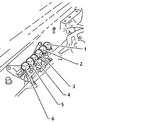
Relay Box Diagram (2002-2004)

Relays

Assignment of the relays in the engine compartment (2002-2004)

Fuse Data
Full access is available to registered users — log in or register.
Log in or register

No.Description
1Vehicle Security Lamp Relay (KA24DE)
2Park/Neutral position (PNP) Relay (A/T) (VG33E and VG33ER) or Clutch Interlock Relay (M/T)
3Horn Relay
4A/C Air Conditioner Relay
5Vehicle Security Lamp Relay (VG33E and VG33ER)
6Fog Lamp Relay (VG33E and VG33ER)

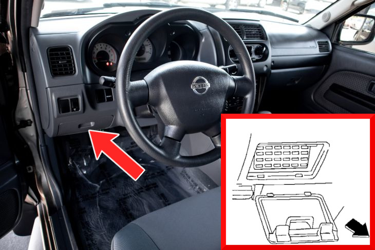
Passenger Compartment

Fuse Box Location

The fuse box is behind the cover positioned below and left of the steering wheel.

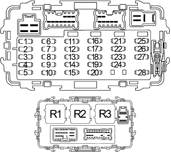
Fuse Box Diagram

Fuses

Assignment of the fuses in the passenger compartment

Fuse Data
Full access is available to registered users — log in or register.
Log in or register

No.AmpsDescription
115AFuel Pump Relay
27.5AHazard Switch
310AInjectors
4
57.5A / 10A1999-2000 (7.5A): ASCD Brake Switch (Shift Lock Brake Switch), Theft Warning Relay, SECU, ASCD Main Switch, Warning Chime Unit, Power Window Relay, Daytime Light Control Unit
2001-2004 (10A): ASCD Brake Switch (Shift Lock Brake Switch), Vehicle Security Relay, SECU, ASCD Control Unit, Warning Chime Unit, Rear Window Defogger Relay, Rear Window Defogger Timer, Low Tire Pressure Warning System, Daytime Light Control Unit, Overdrive Hold Control Module (KA24DE + Automatic Transmission)
620AFront Wiper Motor, Front Washer Motor, Front Wiper Switch
77.5AEngine Control Module (ECM), Daytime Light Control Unit
810AABS, Pressure Switch
910AAir Bag Diagnosis Sensor Unit
1010ARear Wiper Motor, Rear Washer Motor
1110ACombination Meter, Clutch Interlock Relay, 4WD Switch, Back-Up Lamp Switch, Transfer Neutral Position Switch, CAN Converter, Steering Wheel Angle Sensor, Compass and Thermometer, Data Link Connector
1210APark/Neutral Position Switch, Transmission Control Module (TCM)
1310AEngine Control Module (ECM), EGRC Solenoid Valve, EVAP Canister Vent Control Valve, Vacuum Cut Valve Bypass Valve, Supercharger Bypass Valve Control Solenoid Valve, Map/Baro Switch Solenoid Valve
1415AHeated Oxygen Sensor
1510AIACV-AAC Valve, Throttle Position Sensor
16
1710AHazard Switch, Multi-Remote Control Relay (1999-2000)
1810AAudio, Door Mirror Switch, Power Socket Relay (1999-2000)
1915ABlower Motor
207.5ALow Tire Pressure Warning System (2003-2004), SECU

2115A1999-2001: Rear Window Defogger Relay
2220AStop Lamp Switch, Trailer Tow Control Unit
2315ACigarette Lighter
2415ABlower Motor
2515A / 20A1999-2001 (15A): Rear Window, Rear Window Defogger Relay
2002-2004 (20A): Rear Window Defogger Relay
267.5AData Link Connector, Map Lamp, Room Lamp, Low Tire Pressure Warning System (2003-2004)
2710AEngine Control Module (ECM), ECM Relay (ECCS Relay)
287.5ACombination Meter, Key Switch, Security Indicator Lamp, SECU, Transmission Control Module (TCM)

Relays

Assignment of the relays in the passenger compartment

Fuse Data
Full access is available to registered users — log in or register.
Log in or register

No.Description
R1Accessory
R2Blower
R3Ignition

FAQ

Scroll to Top