Looking for Volkswagen Passat fuse box diagrams? This article covers the facelifted eighth-generation Volkswagen Passat (Model Code: B8), produced from 2019 to 2023, and includes fuse box diagrams for Volkswagen Passat (B8) 2019, 2020, 2021, 2022 and 2023, along with details about the location of the fuse panels inside the vehicle and a clear explanation of the assignment of each fuse and relay (fuse layout).
If battery in engine compartment: Heated rear window relay Terminal 15 voltage supply relay Relay for power sockets Fuses 4 to 14, 31 to 35, 38 to 42, 47 to 49, 53 on fuse holder C
80A
If battery in luggage compartment: Radiator fan
125A
Hybrid Drive: Radiator fan
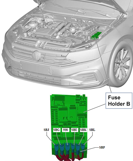
SBG
400A
If battery in engine/luggage compartment: Alternator with voltage regulator
400A
Hybrid Drive: Power and control electronics for electric drive
508
–
If battery in engine compartment: Threaded connection (30), on E-box – Battery
–
Hybrid Drive and If battery in luggage compartment: Threaded connection (30), on E-box – Fuse 3 on fuse holder G, Jump start connection
SBE
80A
If battery in engine compartment: Power steering control unit
–
Hybrid Drive and If battery in luggage compartment: Not Assigned
SBK
80A
If battery in engine compartment: Fuses 15 to 20, 23 to 28, 43 to 45 on fuse holder C
80A
Hybrid Drive and If battery in luggage compartment: Power steering control unit
SBL
50A
If battery in engine/luggage compartment: Radiator fan
80A
Hybrid Drive: Radiator fan
SBP
–
If battery in engine/luggage compartment: Not Assigned
50A
Hybrid Drive: Mechatronic unit for dual clutch gearbox
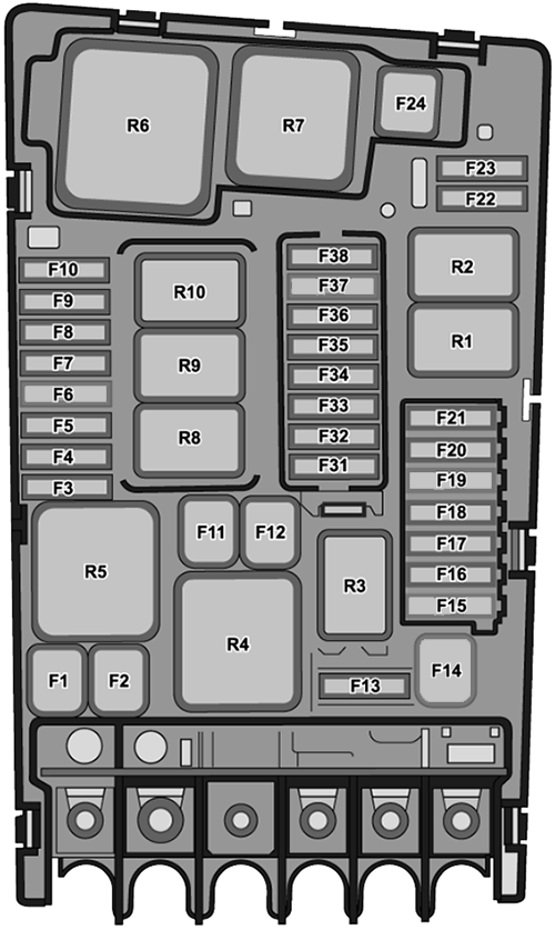
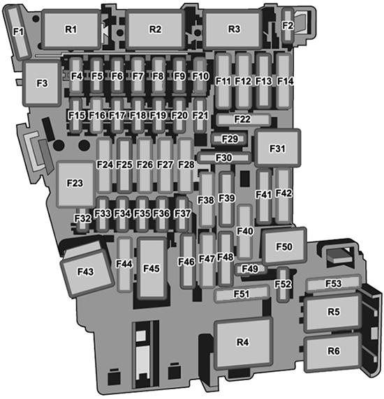
Main Fuse Box Diagram
Fuses
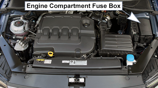
Assignment of the fuses in the engine compartment fuse box (B)
Fuse Data
Full access is available to registered users — log in or register.
petrol (all years), diesel with emissions standard EU6 AP (from Nov 2020): Engine/motor control unit
30A
diesel (up to Nov 2020), diesel except emissions standard EU6 AP (from Nov 2020): Engine/motor control unit
SB4
7.5A (diesel) 10A (petrol)
Air mass meter, Oil level and oil temperature sender, Changeover valve, Camshaft control valve 1, Turbocharger air recirculation valve, Fuel pressure regulating valve, Fuel metering valve, Intake manifold flap valve, Exhaust camshaft control valve 1, Valve for oil pressure control, Coolant valve for cylinder head, Turbine changeover valve, Inlet camshaft control valve 1, Charge pressure control solenoid valve, Activated charcoal filter solenoid valve 1, Charge air cooling pump, Auxiliary pump for heating, Coolant circulation pump, Radiator fan diesel: Automatic glow period control unit, Low and high heat output relay, Glow plug 1 and 3 2.0L petrol: Air conditioning system relay, Engine component power supply relay (from Nov 2020)
SB5
10A
Fuel pressure regulating valve, Fuel metering valve, Injector 2 (cylinder 1 to 4), Inlet and exhaust cam actuator A and B (cylinder 1 to 4), Charge pressure control solenoid valve, Coolant pump for high-temperature circuit diesel: Glow plug 2
SB6
7.5A
Brake pedal switch
SB7
10A 7.5A 15A (2.0L bi-turbo, hybrid)
Changeover valve, Turbocharger air recirculation valve, Intake manifold flap valve, Exhaust gas recirculation cooler changeover valve, Valve for oil pressure control, Coolant valve for gearbox, Coolant valve for cylinder head, Actuator for engine temperature regulation, Piston cooling jet control valve, Heater element for crankcase breather, Coolant shut-off valve, Glow plug 1, Coolant pump, Charge air cooling pump, Auxiliary pump for heating hybrid: Coolant pump for low-temperature circuit 2.0L petrol (from Nov 2020): Coolant circulation pump
SB8
10A 15A
Particulate sensor, NOx sender 3, Lambda probe 1 before and after catalytic converter, Control unit 1 and 2 for NOx sender
SB9
10A (petrol, 2.0L petrol) 20A (petrol)
Ignition coil 1 to 4 with output stage, Camshaft control valve 1, Exhaust camshaft control valve 1, Activated charcoal filter solenoid valve 1, Auxiliary pump for heating, Coolant circulation pump
SB10
15A (petrol) 20A (diesel)
Fuel pump control unit
SB11
40A (diesel)
Auxiliary air heater element
SB12
40A (diesel)
Auxiliary air heater element
SB13
7.5A (hybrid) 30A
Auxiliary hydraulic pump 1 for gearbox oil
SB14
40A
Heated windscreen relay
SB15
15A
Horn relay
SB16
10A (hybrid) 20A (2.0L petrol)
hybrid: Charging unit 1 for high-voltage battery 2.0L petrol: Engine component power supply relay
SB17
7.5A
ABS control unit, Main relay, Heated windscreen relay, Engine/motor control unit
SB18
7.5A
Data bus diagnostic interface Battery monitor control unit
Engine/motor control unit special equipment: Voltage stabiliser
SB23
30A
Starter
SB24
40A (diesel)
Auxiliary air heater element
SB31
10A
hybrid: Fuel tank shut-off valve, Coolant circulation pump before power and control electronics for electric drive, Coolant pump for high-voltage battery
Steering column electronics control unit (heated steering wheel)
SC3
–
–
SC4
7.5A
Alarm horn
SC5
7.5A
Data bus diagnostic interface
SC6
7.5A
Selector lever
SC7
10A
Operating and display unit for rear air conditioning system Heater and air conditioning controls Heated rear window relay Magnetic clutch relay Tyre Pressure Monitoring System control unit Remote control receiver for auxiliary coolant heater
SC8
7.5A
Electromechanical parking brake button Rotary light switch Anti-theft alarm sensor Air humidity, rain and light sensor Control unit for cornering light and headlight range control Dash panel contour lighting Front and rear door contour lighting Diagnostic connection Front roof module
SC9
7.5A
Steering column electronics control unit
SC10
up to July 2021: 7.5A from July 2021: 10A
Display unit for front information display and operating unit control unit Control unit for Head-up Display
SC11
40A
Onboard supply control unit – exterior lighting on the left side (silver-plated contacts)
SC12
20A
Control unit 1 for information electronics
SC13
25A
Front seat belt (driver and passenger side)
SC14
40A
Fresh air blower control unit (silver-plated contacts)
SC15
10A
Control unit for electronic steering column lock
SC16
7.5A
up to June 2020: Storage compartment with interface for mobile telephone USB hub Aerial amplifier for mobile telephone
7.5A
from June 2020: Storage compartment with interface for mobile telephone USB hub Aerial amplifier for mobile telephone TV tuner
10A
from July 2022: Storage compartment with interface for mobile telephone Aerial amplifier for mobile telephone TV tuner USB charging socket 1 USB connection 1
SC17
7.5A
Emergency call module control unit and communication unit Dash panel insert
SC18
7.5A
Rear lid handle Control unit for overhead view camera Rear lid power opening control unit
SC19
7.5A
Driver and front passenger exterior door handle (near field communication) Entry and start authorisation control unit
SC20
7.5A 10A (depending on equipment)
diesel: Relay for reducing agent metering system
SC21
15A
All-wheel drive control unit
SC22
15A
Trailer detector control unit
SC23
20A
Sliding sunroof adjustment control unit
SC24
40A
Onboard supply control unit – exterior lighting on the right side (silver-plated contacts)
SC25
30A
Door control units (driver, passenger, rear left, rear right)
SC26
30A
Onboard supply control unit – seat heating
SC27
30A
Onboard supply control unit – interior lighting
SC28
25A
Trailer detector control unit
SC29
–
–
SC30
10A
hybrid: High-voltage battery 1 Maintenance connector for high-voltage system
SC31
30A
Rear lid control unit
SC32
up to July 2021: 7.5A from July 2021: 7.5A 10A (depending on equipment)
Adaptive cruise control unit Parking aid control unit Lane change assist control unit 1 and 2 Front camera for driver assist systems
SC33
7.5A
Airbag control unit Airbag warning lamp
SC34
7.5A
Electromechanical parking brake button Switch module 2 in centre console Interior mirror Reversing light switch Pressure sender for refrigerant circuit External air quality and air humidity sensor Relay for power sockets Control unit for structure-borne sound
SC35
7.5A
Diagnostic connection
SC36
–
–
SC37
–
–
SC38
25A
Trailer detector control unit
SC39
30A
Door control units (driver, passenger, rear left, rear right)
SC40
20A
12 V sockets 1, 2, and 3 *Note: Factory supplied via terminal 15. Can be reconnected to terminal 30, but ensure consumers are disconnected when engine is off to prevent battery discharge.
SC41
25A
Front seat belt (driver and passenger side)
SC42
40A
Onboard supply control unit – central locking system (silver-plated contacts)
SC43
up to June 2020: 30A from June 2020: 40A
Digital sound package control unit
SC44
15A
Trailer detector control unit
SC45
15A
Driver and front passenger seat adjustment and lumbar support switches Massage control unit Driver seat adjustment control unit Front left seat backrest and cushion fan 1
SC46
30A
up to June 2020: DC/AC converter with socket, 12 V – 230 V
7.5A
from June 2020: USB charging socket 1
–
from July 2022: Not Assigned
SC47
7.5A (Saloon) 15A (Estate)
Rear roller blind control unit (Saloon) Rear window wiper motor (Estate)
SC48
7.5A
Engine sound generator control unit
SC49
7.5A
up to June 2020: High-voltage battery 1 (hybrid) Clutch position sender
7.5A
from June 2020: High-voltage battery 1 (hybrid) Clutch position sender Starter relay 2
SC50
–
–
SC51
25A
Operating and display unit for rear air conditioning system
SC52
15A
Electronically controlled damping control unit
SC53
30A
Heated rear window relay
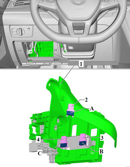
Relays
Assignment of the relays in the passenger compartment fuse box (C)
Fuse Data
Full access is available to registered users — log in or register.
Front passenger seat adjustment thermal fuse 1 – Front passenger seat lumbar support adjustment switch, Front passenger seat adjustment operating unit, Front right seat backrest fan 1, Front right seat cushion fan 1
B
–
–
C
7.5A
up to June 2020: USB charging socket 1
30A
from June 2020: DC/AC converter with socket, 12 V – 230 V
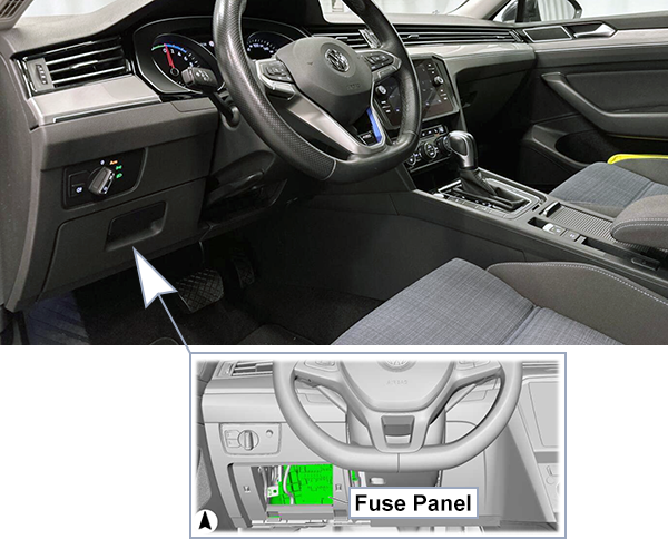
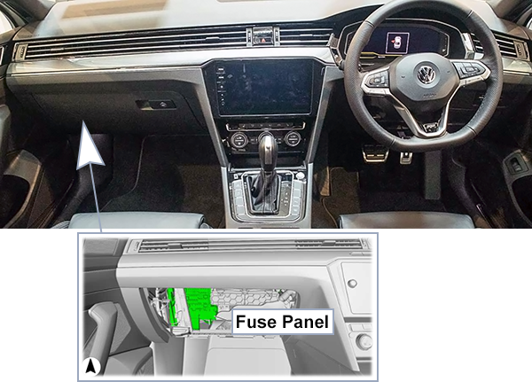
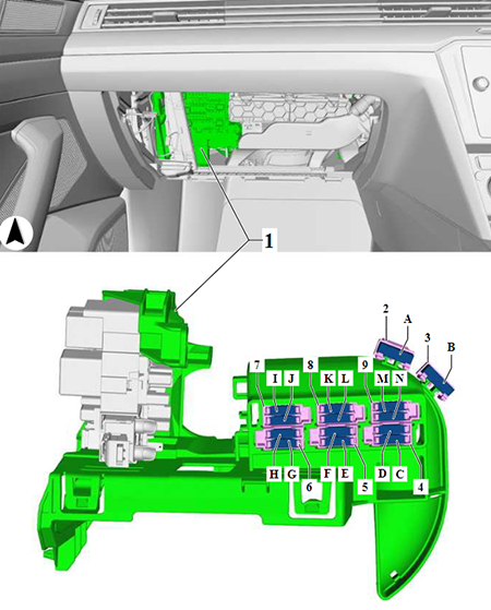
Location and Diagram (RHD)
Fuses
Assignment of the single fuses in the passenger compartment fuse box (Right-Hand Drive)
Fuse Data
Full access is available to registered users — log in or register.
Front passenger seat adjustment thermal fuse 1 – Driver seat lumbar support adjustment switch, Driver seat adjustment operating unit, Front left lumbar support adjustment switch, Massage control unit, Driver seat adjustment control unit, Front right seat backrest fan 1, Front right seat cushion fan 1
B
–
–
C
–
–
D
–
–
E
–
–
F
–
–
G
–
–
H
7.5A
up to June 2020: USB charging socket 1
–
from June 2020: Not Assigned
I
–
–
J
–
up to June 2020: Not Assigned
7.5A
from June 2020: DC/AC converter with socket, 12 V – 230 V
K
–
–
L
–
–
M
–
–
N
–
–
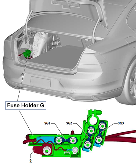
Luggage Compartment (-SG-)
Location and Diagram
Only for models with battery in luggage compartment.
Fuses
Assignment of the fuses in the luggage compartment fuse box (Only for model with battery in luggage compartment)
Fuse Data
Full access is available to registered users — log in or register.
Fuse 15 on fuse holder C -SC15- to fuse 20 on fuse holder C -SC20- Fuse 23 on fuse holder C -SC23- to fuse 28 on fuse holder C -SC28- Fuse 43 on fuse holder C -SC43- to fuse 45 on fuse holder C -SC45-
SG2
125A
Heated rear window relay -J9- Terminal 15 voltage supply relay -J329- Relay for power sockets -J807- Fuse 4 on fuse holder C -SC4- to fuse 14 on fuse holder C -SC14- Fuse 31 on fuse holder C -SC31- to fuse 35 on fuse holder C -SC35- Fuse 38 on fuse holder C -SC38- to fuse 42 on fuse holder C -SC42- Fuse 47 on fuse holder C -SC47- to fuse 49 on fuse holder C -SC49- Fuse 53 on fuse holder C -SC53-
SG3
125A
High heat output relay -J360- Horn relay -J413- Starter relay 1 -J906- Starter relay 2 -J907- Fuse G on fuse holder B -SBG- Fuse E on fuse holder B -SBE- Fuse J on fuse holder B -SBJ- Fuse K on fuse holder B -SBK- Fuse L on fuse holder B -SBL- Fuse P on fuse holder B -SBP- Fuse 11 on fuse holder B -SB11- Fuse 12 on fuse holder B -SB12- Fuse 16 on fuse holder B -SB16- to Fuse 23 on fuse holder B -SB23-
Additional Fuses for Hybrid Drive
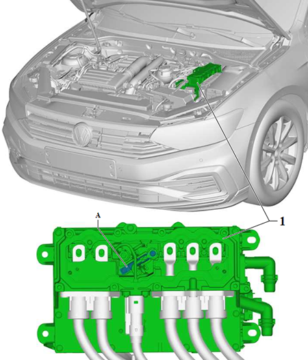
High-Voltage System Location and Diagram
Fuses
Assignment of the additional fuse in the engine compartment fuse box (for Hybrid Drive System)
Fuse Data
Full access is available to registered users — log in or register.
Main relay -J271- Fuse 13 on fuse holder B -SB13- Fuse 14 on fuse holder B -SB14- to Fuse 21 on fuse holder B -SB21- Fuse G on fuse holder B -SBG- Fuse J on fuse holder B -SBJ- Fuse K on fuse holder B -SBK- Fuse 33 on fuse holder B -SB33- to fuse 38 on fuse holder B -SB38-
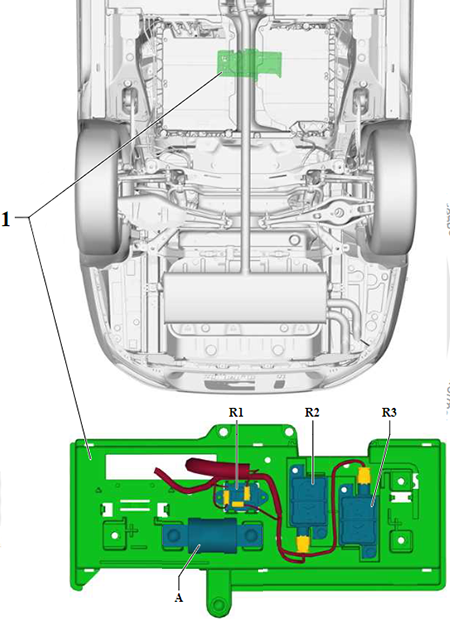
Switching Unit Location and Diagram
Switching unit for high-voltage battery -SX6-.
High Voltage Fuse
Assignment of the fuses in fuse box under the vehicle (for Hybrid Drive System)
Fuse Data
Full access is available to registered users — log in or register.


 | 2019-2022")