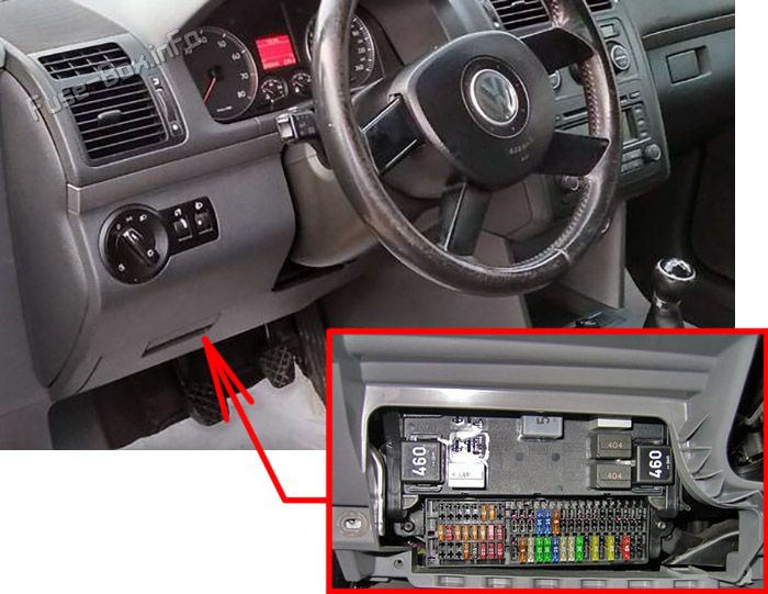
Looking for Volkswagen Touran fuse box diagrams? This article covers the first-generation Volkswagen Touran (Model Code: 1T), produced from 2003 to 2006, and includes fuse box diagrams for Volkswagen Touran (1T) 2003, 2004, 2005 and 2006, along with information about the location of the fuse panels inside the vehicle and a clear breakdown of the assignment of each fuse and relay (fuse layout).
Tank leak diagnosis Lambda probe 1 heater, downstream of catalytic converter Electrical/pneumatic valve block (only AVQ and AZV) Secondary air pump relay (only with BGU)
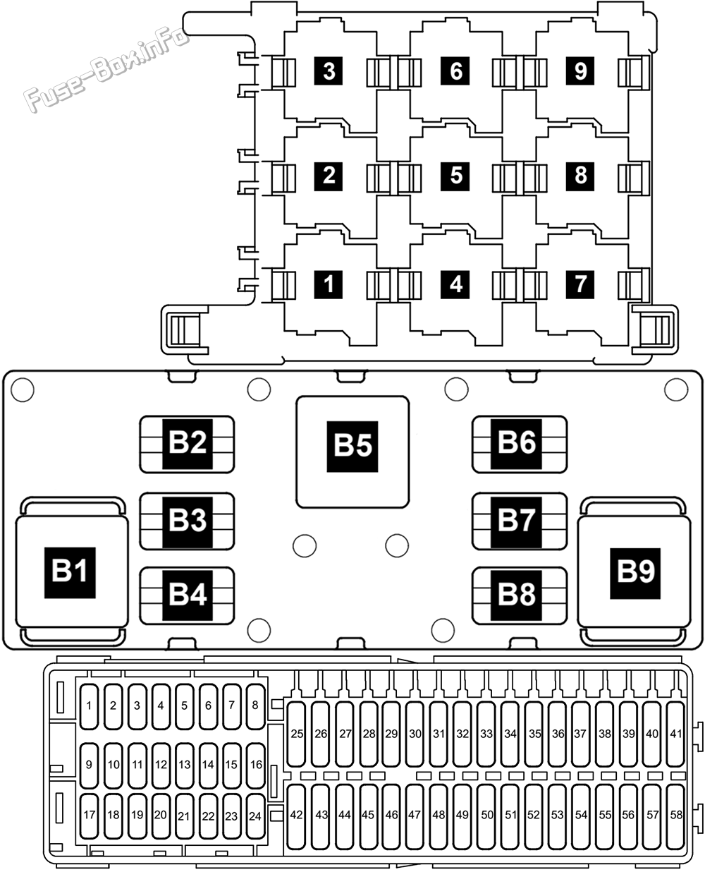
10A
F11
Motronic control unit Diesel direct injection system control unit Simos control unit
25A
F12
Lambda probes (does not BGU) Lambda probe after catalyst (does not BGU) NOx sensor control unit
15A
F13
Automatic gearbox control unit
30A
F14
–
–
F15
Starter (terminal 50)
25A
F16
Heated steering wheel
15A
F17
Control unit with display in dash panel insert
10A
F18
Terminal 15 voltage supply relay
30A
F19
Radio
15A
F20
Telephone/preparation for telephone
10A
F21
TV tuner
10A
F22
–
–
F23
Distance regulation control unit
10A
F24
Data bus diagnostic interface
10A
F25
–
–
F26
Motronic control unit Diesel direct injection system control unit
10A
F27
Heater element (crankcase breather)
10A
F28
Automatic gearbox control unit
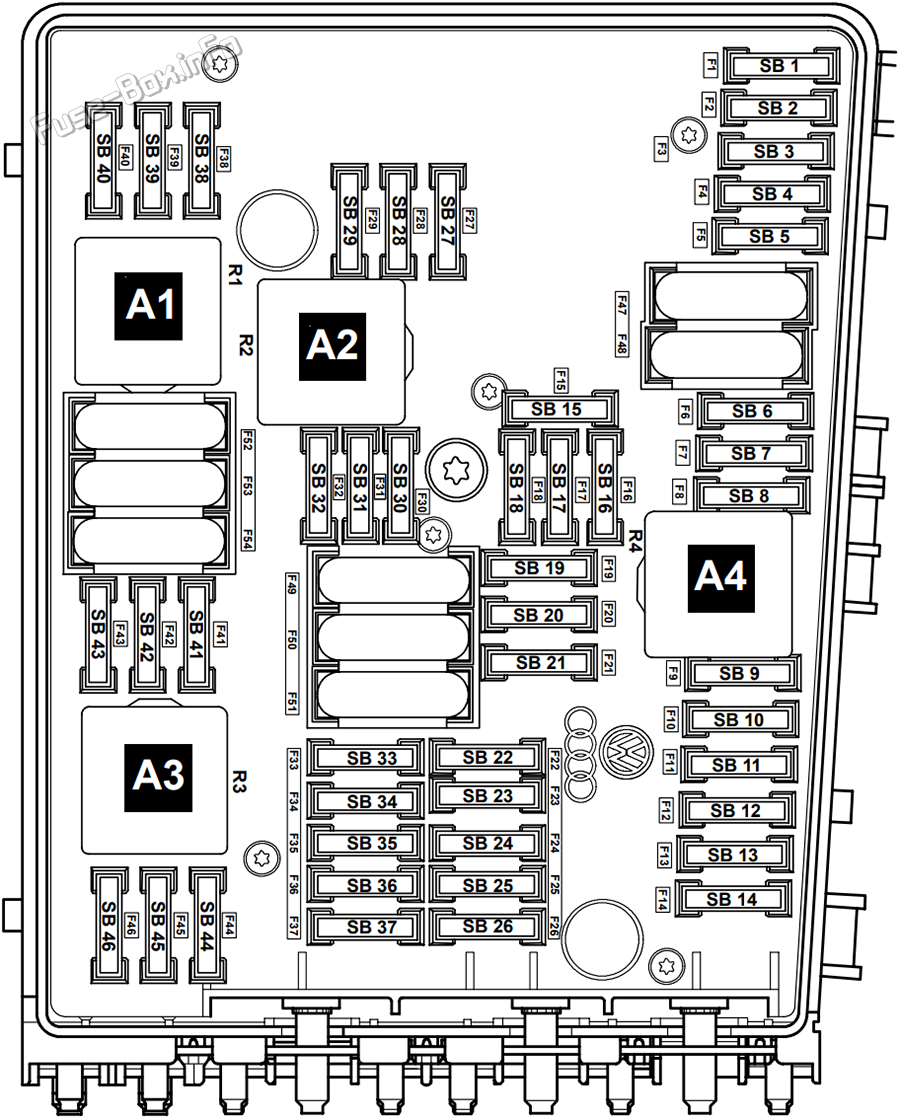
F29
Ignition coil 1 with output stage (only BAG) Ignition coil 2 with output stage (only BAG) Ignition coil 3 with output stage (only BAG) Ignition coil 4 with output stage (only BAG)
20A
F30
Heater control unit
5A
F31
Windscreen wiper motor, driver’s side
25A
F32
Injectors (does not BAG) Glow plug relay (only with AVQ and AZV)
10A
F33
Fuel pump relay (does not BAG) Glow plug 2 relay (only with AVQ and AZV)
15A
F34
–
–
F35
–
–
F36
–
–
F37
Glow plugs -1-
30A
F38
Headlight range control motor, left (does not gas discharge headlight) Headlight range control motor, right (does not gas discharge headlight)
10A
F39
Control unit with display in dash panel insert Oil level/oil temperature sender
5A
F40
Ignition system
20A
F41
–
–
F42
Air mass meter Fuel pump relay Current supply relay for Simos control unit
5A
F43
Vacuum pump
20A
F44
–
–
F48
Onboard power supply control unit
40A
F49
Onboard power supply control unit
50A
F50
Amplifier
10A
F51
Coolant heater element relay Secondary air pump motor
40A
F52
–
–
F53
Door control unit
50A
F54
Radiator fan-end stage Radiator fan – end stage
50A
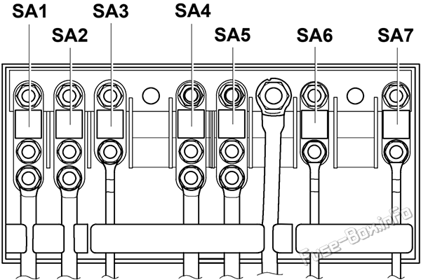
Relays
Assignment of the relays in the engine compartment fuse box
Fuse Data
Full access is available to registered users — log in or register.