Looking for Buick Enclave fuse box diagrams ? This article covers the facelifted second-generation Buick Enclave , available from 2022 , and includes fuse box diagrams for Buick Enclave 2022, 2023 and 2024 , along with details about the location of the fuse panels inside the vehicle and a clear explanation of the assignment of each fuse and relay (fuse layout).
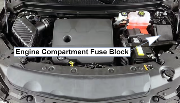
The under-hood fuse block is in the engine compartment, on the driver side of the vehicle. To remove the fuse block cover, press the clips on the cover and lift it straight up.
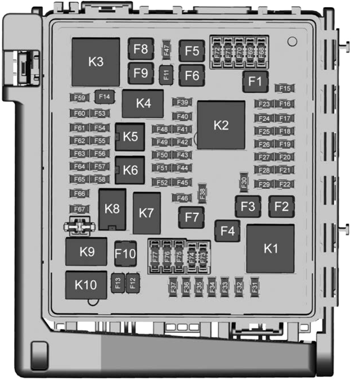
Do not pull the engine compartment fuse block lever, since it is intended only for service purposes. If pulled, vehicle malfunction may occur. Assignment of the fuses in the engine compartment
Fuse Data
Full access is available to registered users — log in or register.
Log in or register
No. Description F1 Antilock Brake System Pump F2 Starter 1 F3 DC DC Transformer 1 F4 – F5 DC DC Transformer 2 F6 – F7 – F8 – F9 Vacuum Pump F10 Front Wiper F11 – F12 – F13 Starter 2 F14 – F15 Rear Wiper F16 – F17 – F18 – F19 – F20 – F21 – F22 Electronic Brake Control Module F23 Parking/Trailer Lamps F24 Right Trailer Stoplamp / Turnlamp F25 Steering Column Lock F26 – F27 Left Trailer Stoplamp / Turnlamp F28 – F29 – F30 Washer Pump F31 – F32 Left Low-Beam Headlamp F33 Daylight Running Lamps F34 Horn F35 – F36 – F37 Right Low-Beam Headlamp F38 Automatic Headlamp Leveling Motor F39 Transmission Control Module F40 Left Rear Bus Electrical Center / lgnition F41 Instrument Cluster F42 Heating, Ventilation, and Air Conditioning F43 Head-up Display / Reflective Light Auxiliary Display F44 Communication Gateway Module / Run/Crank F45 – F46 – F47 – F48 – F49 Interior Rearview Mirror F50 Fuel Tank Zone Module / Shifter Interface Board / Run/Crank F51 Heated Steering Wheel F52 Folding Seats Switch F53 Coolant Pump F54 – F55 Air Conditioning Clutch F56 – F57 Engine Control Module / Ignition F58 Transmission Control Module / lgnition F59 Engine Control Module Battery F60 Engine Control Module – Even F61 O2 Sensor 1 / Air Flow F62 – F63 O2 Sensor 2 / Canister / Engine Oil / Turbo F64 Aeroshutter F65 Engine Control Module Powertrain 1 F66 Engine Control Module Powertrain 2 F67 Engine Control Module – Odd F68 – F69 – F70 – F71 – F72 – F73 – F74 – F75 – F76 – F77 –
This content requires JavaScript and a valid membership to view.
Assignment of the relays in the engine compartment
Fuse Data
Full access is available to registered users — log in or register.
Log in or register
No. Description K1 Starter 1 K2 Run/Crank K3 Vacuum Pump K4 – K5 Air Conditioning K6 – K7 Engine Control Module K8 Folding Seats K9 – K10 Starter 2
This content requires JavaScript and a valid membership to view.
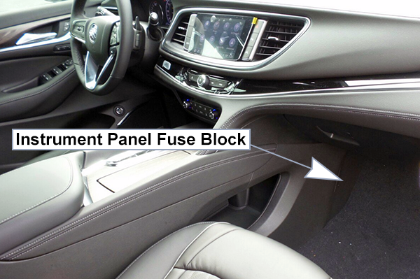
The instrument panel fuse block is inside the center console on the passenger side of the vehicle. Remove the fuse access door by pulling the door at the opening.
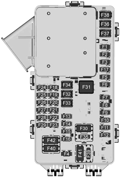
Assignment of the fuses in the passenger compartment
Fuse Data
Full access is available to registered users — log in or register.
Log in or register
No. Description F1 Body Control Module 6 F2 Diagnostic Link F3 Electric Steering Column Lock F4 Rear USB Port F5 Rear Sunshade / Park/Reverse/Neutral/Drive/Low F6 Heating, Ventilation, and Air Conditioning F7 Body Control Module 3 F8 Adaptive Front Lighting System F9 Right Front Heated Seat F10 Airbag F11 – F12 Amplifier F13 Body Control Module 7 F14 Left Front Heated Seat F15 – F16 Sunroof F17 Communication Gateway Module F18 Instrument Cluster / Head Up Display F19 Body Control Module 1 F20 Wireless Charger Module F21 Body Control Module 4 F22 Infotainment F23 Body Control Module 2 F24 Park/Reverse/Neutral/Drive/Low F25 Park Assist / Shifter Interface Board F26 Communications Integration Module F27 Video F28 Radio / Heating, Ventilation, and Air Conditioning Display F29 Radio F30 Steering Wheel Controls F31 Front Blower F32 DC AC Inverter F33 Driver Power Seat F34 Passenger Power Seat F35 Feed / Body Control Module 4 F36 Electric Power Steering F37 Power Outlet / Wireless Charger / Accessory F38 Body Control Module 8 F39 –
This content requires JavaScript and a valid membership to view.
Assignment of the circuit breakers in the passenger compartment
Fuse Data
Full access is available to registered users — log in or register.
Log in or register
No. Description F40 – F41 – F42 Auxiliary Power Outlet (CB) / Lighter (Minifuse)
This content requires JavaScript and a valid membership to view.
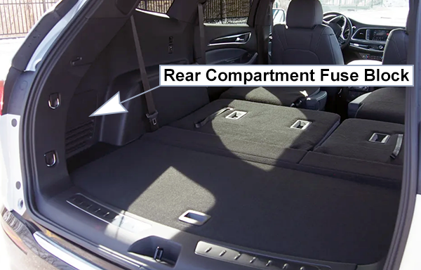
The rear compartment fuse block is behind a trim panel on the driver side of the rear storage compartment. The trim panel is removed by prying along the top edge of the trim panel at two notched locations.
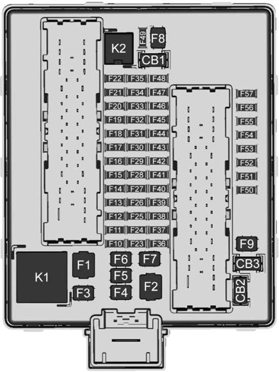
Assignment of the fuses in the rear compartment
Fuse Data
Full access is available to registered users — log in or register.
Log in or register
No. Description F1 – F2 Trailer F3 Folding Seats F4 Rear Blower F5 Rear Drive Control F6 – F7 Right Window F8 Rear Defogger F9 Left Window F10 – F11 Trailer Reverse F12 USB Port / Third Row Seats F13 – F14 – F15 – F16 – F17 – /Air Quality Sensor F18 – F19 Ventilated Seats / Massage F20 – F21 – F22 – F23 – F24 Lumbar F25 – F26 Trailer Brake Lamps F27 Massage F28 Passive Entry / Passive Start F29 – F30 Canister Vent F31 – F32 Heated Mirrors F33 USB Port / Second Row Seats F34 Liftgate Module F35 Fuel System Control Module / Fuel Tank Zone Module F36 – F37 – F38 Window Module F39 Rear Closure F40 Memory Seat Module F41 Automatic Occupancy Sensor F42 – F43 – F44 – F45 Liftgate Motor F46 Rear Heated Seats F47 – F48 – F49 – F50 – F51 – F52 Semi-Active Dampening System Module F53 – F54 External Object Calculating Remote System / Side Blind Zone Alert F55 – F56 Universal Remote System / Overhead Console / Humidity/Rain Sensor F57 Hands Free Closure Release
This content requires JavaScript and a valid membership to view.
Assignment of the circuit breakers in the rear compartment
Fuse Data
Full access is available to registered users — log in or register.
Log in or register
No. Description CB1 – CB2 – CB3 Rear Auxiliary Power Outlet
This content requires JavaScript and a valid membership to view.
Assignment of the relays in the rear compartment