Looking for Volkswagen Passat fuse box diagrams ? This article covers the fourth-generation Volkswagen Passat (Model Codes: B5, 3B) before the facelift , produced from 1997 , and includes fuse box diagrams for Volkswagen Passat (B5) 1997, 1998, 1999, 2000 and 2001 , along with details about the location of the fuse panels inside the vehicle and a clear explanation of the assignment of each fuse and relay (fuse layout).
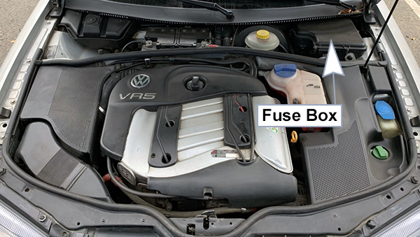
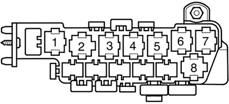
The fuse block is located in a protective housing for the control module, in the plenum on the driver side.
Assignment of the fuses in engine compartment
Fuse Data
Full access is available to registered users — log in or register.
Log in or register
Amps Description 15A Engine Control Module (ECM) 40A Glow Plug Fuse – Engine 40A Glow Plug Fuse – Engine 25A Glow Plug Fuse – Coolant 50A Glow Plug -2- Fuse – Coolant
This content requires JavaScript and a valid membership to view.
Assignment of the relays in engine compartment
Fuse Data
Full access is available to registered users — log in or register.
Log in or register
Description Relay For Preheating, Low Heat Output (373) Relay For Preheating, High Heat Output (370) Power Supply (Terminal 30, B+) Relay (219) Secondary Air Pump Relay (203)
This content requires JavaScript and a valid membership to view.
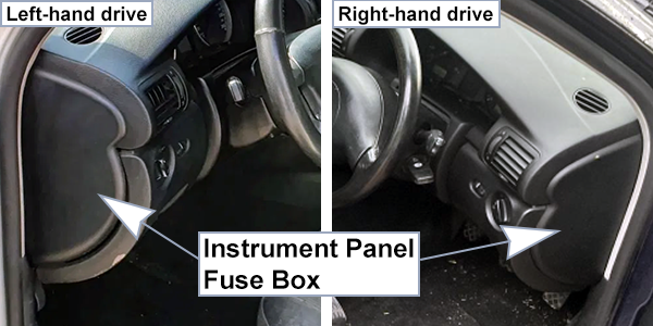
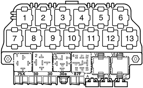
The fuse panel is located under a cover at the end of the dashboard on the driver’s side.
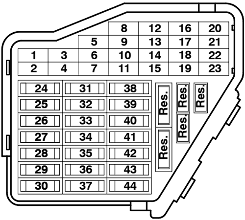
Assignment of the fuses in the dashboard
Fuse Data
Full access is available to registered users — log in or register.
Log in or register
No. Amps Description 1 5A Heated washer nozzle 2 10A Turn signal system 3 5A Light for glove compartment, air conditioning, selector lever 4 5A License plate light 5 10A Instr. cluster, heated seats, cruise control test plug, air conditioning 6 5A Control module comfort system 7 10A ABS 8 5A Automatic headlight beam adjusting, telephone system 9 10A – 10 5A CD changer unit 11 5A Cruise control by automatic transmission 12 10A B+(battery positiv voltage) for on board diagnostic (OBD) 13 10A Brake lights 14 10A Comfort system 15 10A Instr. cluster, automatic transmission 16 5A – 17 10A Navigation 18 10A Right headlight, high beam 19 10A Left headlight, high beam 20 15A Right headlight, low beam 21 15A Left headlight, low beam 22 5A Parklight, right 23 5A Parklight, left 24 25A Wiper system 25 30A Fresh air blower, recirculating control, air conditioning 26 30A Rear window defogger 27 15A Rear window wiper system 28 15A Fuel pump (FP) 29 20A Engine control 30 20A Sunroof 31 15A Back-up lights, cruise control, automatic transmission 32 20A Engine control 33 15A Cigarette lighter 34 15A Engine control, injectors 35 30A Trailer socket 36 15A Fog lights 37 20A Radio system, telephone system 38 15A Comfort system 39 15A Emergency flasher system 40 25A Dual horn 41 25A – 42 25A – 43 10A – 44 30A Heated seats
This content requires JavaScript and a valid membership to view.
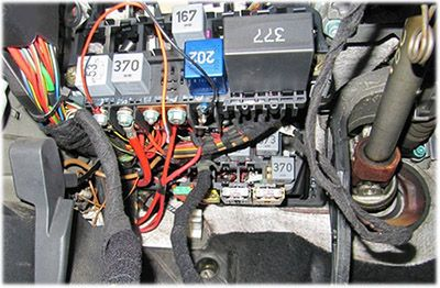
Assignment of the relays on the relay panel under dashboard
Fuse Data
Full access is available to registered users — log in or register.
Log in or register
No. Description 1 Dual Horn Relay (204) 2 Load Reduction Relay (213) 3 – 4 Fuel Pump (FP) Relay (208) V Wiper/Washer Intermittent Relay (377) VI Wiper/Washer Intermittent Relay (377)
This content requires JavaScript and a valid membership to view.
Assignment of the fuses on the relay panel under dashboard
Fuse Data
Full access is available to registered users — log in or register.
Log in or register
ID. Description A Fuse for socket I in luggage compartment B Fuse for socket II in luggage compartment
This content requires JavaScript and a valid membership to view.
Assignment of the relays above the relay panel under dashboard
Fuse Data
Full access is available to registered users — log in or register.
Log in or register
No. Description 1 Coolant Fan Control (FC) A/C Relay (214) 2 Relay for motor remote unlock rear lit (79) 3 A/C Clutch relay (267) 4 A/C Clutch control module relay (384) 5 – 6 Selector Lever Light Relay (205) 7 Fog Light Relay (381) 8 Daytime Running Lights Change-Over Relay (173) 9 – 10 Glow Plug Relay (180) 11 Change Over Relay For Speaker Radio/Telephone 12 Starting Interlock Relay-Alarm System (186) 13 Park/Neutral Position (PNP) Relay (175) Starting Interlock Relay-Clutch Position (204)
This content requires JavaScript and a valid membership to view.
Auxiliary relay panel is located behind the relay panel that’s on top.
Assignment of the fuses behind the relay panel under dashboard
Fuse Data
Full access is available to registered users — log in or register.
Log in or register
Amps Description 5A Coolant Fan 30A Coolant Fan 50A ABS Hydraulic Pump
This content requires JavaScript and a valid membership to view.
Assignment of the relays behind the relay panel under dashboard
Fuse Data
Full access is available to registered users — log in or register.
Log in or register
No. Description 1 – 2 – 3 – 4 – 5 Coolant Fan Control (FC) Relay (214), 80W First Speed Coolant Fan Control (FC) Relay (214), 300W 6 Radiator Fan Afterrun Relay (214) 7 – 8 Second Speed Coolant Fan Control Relay(213), 300W
This content requires JavaScript and a valid membership to view.
")
")
")
")
")

 2019-2022")