Looking for Volkswagen Passat fuse box diagrams ? This article covers the facelifted fourth-generation Volkswagen Passat (Model Codes: B5.5, 3BG) , produced from 2001 , and includes fuse box diagrams for Volkswagen Passat (B5.5) 2001, 2002, 2003, 2004 and 2005 , along with details about the location of the fuse panels inside the vehicle and a clear explanation of the assignment of each fuse and relay (fuse layout).
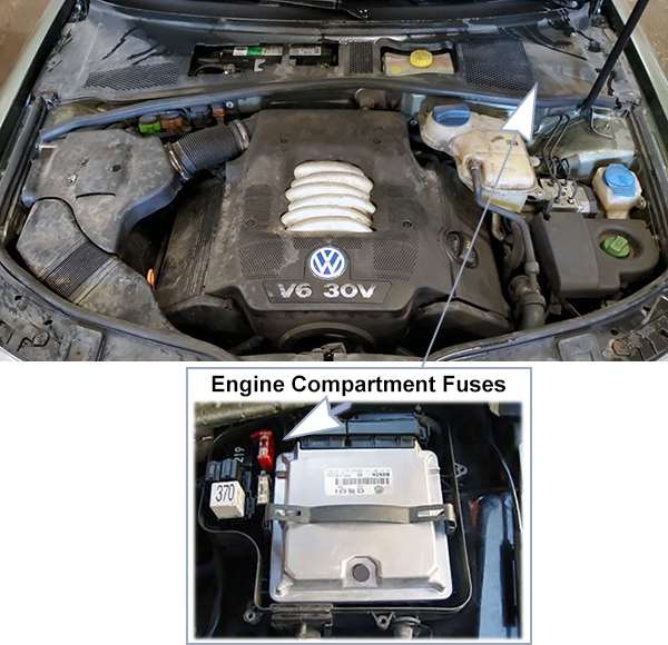
The fuse block is located in a protective housing for the control module, in the plenum on the driver side.
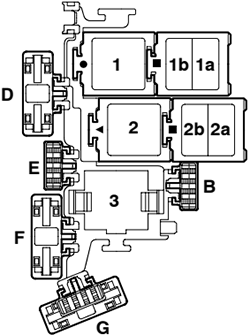
Assignment of the fuses in engine compartment
Fuse Data
Full access is available to registered users — log in or register.
Log in or register
ID. Amps Description B 10A Fuse for Injectors (S116) 5A Fuse for Auxiliary Engine Coolant (EC) Pump D 50A Fuse for Secondary Air Pump (S130) E 40A Fuse for Ignition coil termial (S115) F 5A Engine control Module (ECM) Fuse (S102) G 10A Engine Electronics Fuse (S282)
This content requires JavaScript and a valid membership to view.
Assignment of the relays in engine compartment
Fuse Data
Full access is available to registered users — log in or register.
Log in or register
No. Description 1 Motronic Engine Control Module Power Supply Relay (167), engine code BDP 2 Secondary Air Injection (AIR) Pump Relay (373), (100) 3 Motronic Engine Control Module Power Supply Relay (429), (219) Auxiliary Engine Coolant (EC) Pump Relay (53), (411)
This content requires JavaScript and a valid membership to view.
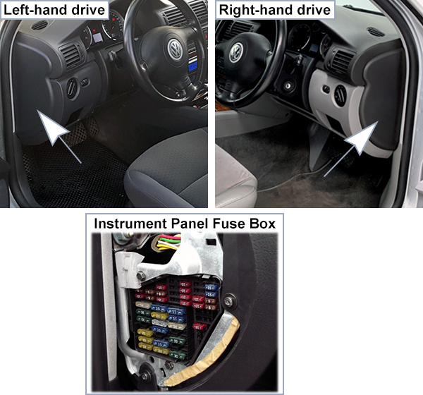
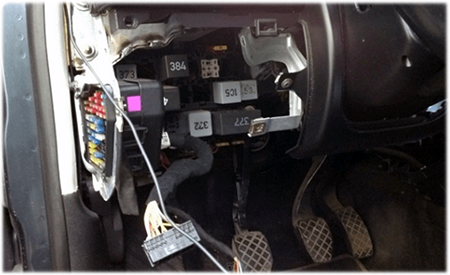
The fuse panel is located under a cover at the end of the dashboard on the driver’s side.
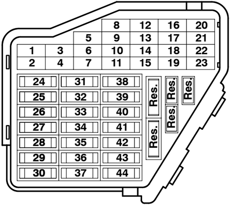
Assignment of the fuses in the dashboard
Fuse Data
Full access is available to registered users — log in or register.
Log in or register
No. Amps Description 1 5A Heated washer nozzle 2 10A Turn signal system 3 – – 4 5A License plate light 5 10A Power Seats, air conditioning, telematics, Multi-Function Steering Wheel, Power sunroof, mirror adjustment, HomeLink 6 5A Comfort module comfort system 7 10A ABS, Cruise Control system, Engine Control Unit 8 5A Automatic headlight beam adjusting 9 5A Parking aid 10 5A CD-Changer Unit, Telematics, Multi-Function Steering Wheel, Navigation, Radio 11 5A Power Seats with Memory 12 10A B+ (battery positive voltage) for Data Link Connector (DLC) 13 10A Brake lights 14 10A Comfort module system 15 10A Instr. cluster, air conditioning, automatic transmission 16 5A ABS, Steering Angle Sensor 17 10A/15A Power outlet, Telematics 18 10A Right headlight, high beam 19 10A Left headlight, high beam 20 15A Right headlight, low beam 21 15A Left headlight, low beam 22 5A Parklight, right 23 5A Parklight, left 24 25A Wiper system 25 30A Fresh air blower, recirculating control, air conditioning, Power sunroof 26 30A Rear window defogger 27 15A Rear window wiper system 28 20A Fuelpump (FP) 29 20A Engine Control Unit, Coolant Fan 30 20A Sunroof 31 15A Back-up lights, Cruise control system, automatic transmission, Mirror adjustments, diagnostic 32 20A Engine Control Module (ECM), Cruise control system 33 15A Cigarette lighter 34 15A Engine Control Module (ECM), injectors 35 30A Trailer socket 36 15A Fog lights 37 20A Radio system, Navigation 38 15A Comfort module system 39 15A Emergency flasher system 40 25A Dual horn 41 25A Telematics 42 25A ABS 43 15A Engine Control Module (ECM) 44 30A Heated seats
This content requires JavaScript and a valid membership to view.
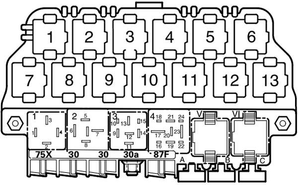
Assignment of the relays located on relay panel under the dashboard
Fuse Data
Full access is available to registered users — log in or register.
Log in or register
No. Description 1 Dual Horn Relay (53) 2 Load Reduction Relay (370) 3 – 4 Fuel Pump (FP) Relay (372) (409) V Wiper/Washer Intermittent Relay (377) (389) Wiper/Washer Intermittent Relay/Rainsensor (192) VI Wiper/Washer Intermittent Relay (377) (389) Wiper/Washer Intermittent Relay/Rainsensor (192)
This content requires JavaScript and a valid membership to view.
Assignment of the fuses located on relay panel under the dashboard
Fuse Data
Full access is available to registered users — log in or register.
Log in or register
ID. Amps Description A 20A Fuse for 12v socket I in luggage compartment B 20A Fuse for 12v socket II in luggage compartment C 10A Fuse for Taxi
This content requires JavaScript and a valid membership to view.
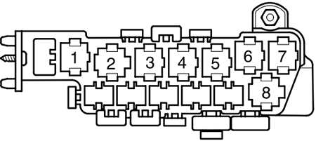
Assignment of the relays located on thirteenfold auxiliary relay panel under the dashboard
Fuse Data
Full access is available to registered users — log in or register.
Log in or register
No. Description 1 Coolant Fan Control (FC) – A/C Relay (373) 2 Sun-Roof Relay (79) 3 A/C Clutch Relay (267) A/C Clutch Relay (384) 4 Daytime Running Lights Change-Over Relay (173) 5 Taxi Alarm Relay High Beam Headlight Relay Emergency Flasher Relay 6 Selector Lever Light Relay 7 Fog Light Relay (381) 8 Control Module for Multi-function steering wheel (451) Control Module for Multi-function steering wheel (452) 9 Control Module for Multi-function steering wheel (451) Control Module for Multi-function steering wheel (452) 10 Brake Booster Relay (373) 11 Taxi Alarm Relay Emergency Flasher Relay (200) 12 Dual Horn Relay (53) Taxi Alarm Relay 13 Park/Neutral Position (PNP) Relay (175) Starting Interlock Relay-Clutch Position (53)
This content requires JavaScript and a valid membership to view.
Assignment of the fuses located on thirteenfold auxiliary relay panel under the dashboard
Fuse Data
Full access is available to registered users — log in or register.
Log in or register
ID. Amps Description A 25A Fuse for Taxi B 20A Fuse for Taxi 10A High Beam Headlight left C 15A Fuse for Brake System Vacuum Pump D 20A Fuse for Power Outlet (12 V) Rear Console E 5A Fuse for Taxi 10A High Beam Headlight right
This content requires JavaScript and a valid membership to view.
Second auxiliary relay panel is located behind first relay panel.
Assignment of the fuses located behind the auxiliary relay panel under the dashboard
Fuse Data
Full access is available to registered users — log in or register.
Log in or register
Amps Description 30A ABS Hydraulic Pump Fuse 30A Power Window Fuse 30A / 40A / 60A Coolant Fan Fuse 5A Coolant Fan Fuse 30A / 50A ABS Hydraulic Pump Fuse 30A Power Seat Circuit Breaker – Passenger’s Seat 30A Power Seat Circuit Breaker – Driver’s Seat 30A Alarm System with Anti-Theft warning system – Telematics 15A Alarm System with Anti-Theft warning system
This content requires JavaScript and a valid membership to view.
Assignment of the relays located behind the auxiliary relay panel under the dashboard
Fuse Data
Full access is available to registered users — log in or register.
Log in or register
No. Description 1 – 2 – 3 Coolant Fan Control (FC) Relay 80 W (373) 4 – 5 First Speed Coolant Fan Control (FC) Relay (373) 6 Coolant Fan Control (FC) Relay (373) 7 Relay for ABS with ESP (373) 8 Coolant Fan Control (FC) Relay (370)
This content requires JavaScript and a valid membership to view.
")
")
")
")
")

 2019-2022")