")
")
")
")
")

 2019-2022")
Looking for Volkswagen Passat fuse box diagrams? This article covers the Volkswagen Passat (Model Code: B6), produced from 2005 to 2010, and includes fuse box diagrams for Volkswagen Passat 2005, 2006, 2007, 2008, 2009 and 2010, along with details about the location of the fuse panels inside the vehicle and a clear explanation of the assignment of each fuse and relay (fuse layout).
What’s Included
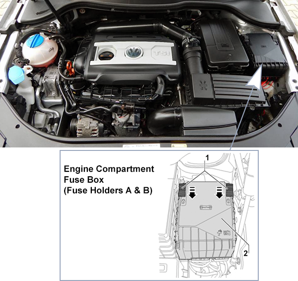
ToggleEngine Compartment
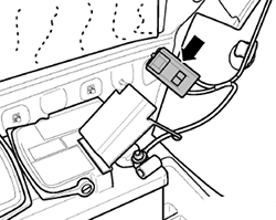
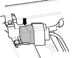
Fuse Box Location
- Open the engine hood.
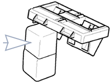
- Move the release buttons (1) in the direction of the arrows to unlock the fuse box cover.
- Remove the cover (2) upward.
- To install, place the cover on the fuse box. Slide release buttons against the direction of the arrows until they latch with an audible “click”.
Pre-Fuse Box Diagram (-SA-) High
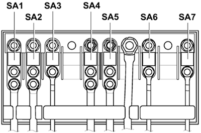
High Voltage Fuses
Assignment of the high voltage fuses in engine compartment pre-fuse box (SA) E-Box High
| No. | Amps | Description |
|---|---|---|
| SA1 | 150A 180A (180A alternator, installed in alternator wire) | Alternator |
| SA2 | 80A | Electromechanical power steering motor |
| SA3 | up to Oct 2005: 80A from Nov 2005: 50A | Radiator fan control unit |
| SA4 | 100A | up to Apr 2006: Driver and front passenger seat adjustment thermal fuse 1 Left fuse holder (SC32 to SC37) Right fuse holder (SD32 to SD37) |
| 80A | May 2006 to Apr 2008: Left fuse holder (SC12 to SC17, SC29 to SC31) Right fuse holder (SD12 to SD17, SD28, SD29 to SD31) | |
| 60A | from May 2008: Right fuse holder (SD1 and SD2) | |
| SA5 | 80A | up to Apr 2008: Right fuse holder (SD22 to SD27) from May 2006: Driver and front passenger seat adjustment thermal fuse 1 |
| SA6 | 100A | up to Apr 2006: Left fuse holder (SC12 to SC17, SC29 to SC31) Right fuse holder (SD12 to SD17, SD28, SD29 to SD31) |
| 80A | from May 2006: Left fuse holder (SC32 to SC37) | |
| SA7 | 40A | ABS control unit |
Pre-Fuse Box Diagram (-SA-) Low
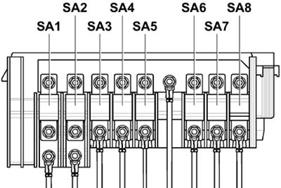
High Voltage Fuses
Assignment of the high voltage fuses in engine compartment pre-fuse box (SA) E-Box Low
| No. | Amps | Description |
|---|---|---|
| SA1 | 150A | Alternator |
| SA2 | 80A | Electromechanical power steering motor |
| SA3 | up to Oct 2005: 80A from Nov 2005: 50A | Radiator fan control unit |
| SA4 | 60A | up to Apr 2006: Driver and front passenger seat adjustment thermal fuse 1 Left fuse holder (SC32 to SC37) Right fuse holder (SD32 to SD37) from May 2006: Left fuse holder (SC12 to SC17, SC29 to SC31) Right fuse holder (SD12 to SD17, SD28, SD29 to SD31) (up to Apr 2008) |
| SA5 | 80A | up to Apr 2008: Right fuse holder (SD22 to SD27) Driver and front passenger seat adjustment thermal fuse 1 (from May 2006) |
| 60A | from May 2008: Driver and front passenger seat adjustment thermal fuse 1 Right fuse holder (SD1 and SD2) | |
| SA6 | 100A | up to Apr 2006: Left fuse holder (SC12 to SC17, SC29 to SC31) Right fuse holder (SD12 to SD17, SD28, SD29 to SD31) |
| 80A | from May 2006: Left fuse holder (SC32 to SC37) | |
| SA7 | 60A 100A (depending on equipment) | Auxiliary battery charge cable Auxiliary air heater heating element High heat output relay (from Nov 2006) |
| SA8 | 40A | ABS control unit |
Fuse Box Diagram (-SB-) High
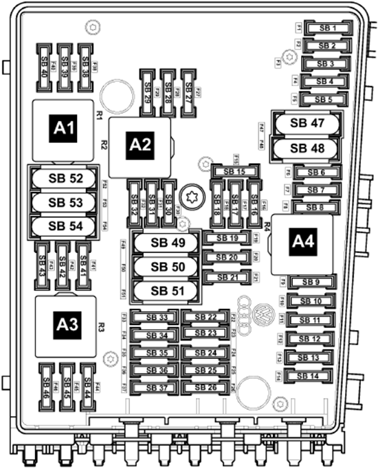
Fuses
Assignment of the fuses in engine compartment fuse box (SB) E-Box High
| No. | Amps | Description |
|---|---|---|
| SB1 | 5A 15A | Automatic gearbox control unit Mechatronic unit for dual clutch gearbox |
| SB2 | 30A | ABS control unit |
| SB3 | 20A | Convenience system central control unit (up to Apr 2006) Trailer detector control unit (from May 2006) |
| SB4 | 5A | Onboard supply control unit |
| SB5 | 20A | Treble tone horn, Bass tone horn |
| SB6 | – | up to Apr 2005: Not Assigned |
| 20A | from May 2005: Ignition coils with output stages | |
| SB7 | – | up to Apr 2005: Not Assigned |
| 15A 5A | from May 2005: Fuel pressure regulating valve Clutch position sender | |
| SB8 | – | up to Apr 2005: Not Assigned |
| 10A | from May 2005: Radiator fan control unit, Activated charcoal filter system solenoid valve 1, Camshaft control valve 1, Intake manifold flap valve, Exhaust camshaft control valve 1, Suction jet pump valve | |
| SB9 | – | up to Apr 2005: Not Assigned |
| 5A | from May 2005: Circulation pump relay | |
| SB10 | – | up to Apr 2005: Not Assigned |
| 10A | from May 2005: Motronic current supply relay 2 | |
| SB11 | – | up to Apr 2005: Not Assigned |
| 25A 30A (diesel) | from May 2005: Engine control unit | |
| SB12 | – | – |
| SB13 | – | – |
| SB14 | – | – |
| SB15 | – | up to Apr 2005: Not Assigned |
| 10A | from May 2005: Circulation pump | |
| SB16 | up to Apr 2005: 10A from May 2005: 5A | Steering column electronics control unit |
| SB17 | 5A | Control unit in dash panel insert |
| SB18 | 30A | Amplifier, Special vehicle control unit |
| SB19 | 15A 20A (RNS 510 and RNS 300, from Nov 2007) | Radio, Control unit with display for radio and navigation system, Control unit with display for TV, radio, navigation (Japan) |
| SB20 | 5A | up to Apr 2005: Aerial selection control unit, Mobile telephone operating electronics control unit |
| 5A | from May 2005: Aerial selection control unit (up to Apr 2006), Telephone transmitter and receiver unit (up to Apr 2006), Operating unit for preparation for mobile telephone (from May 2006), Mobile telephone operating electronics control unit (from May 2006), TV tuner (from Nov 2008), Satellite digital radio tuner (from Nov 2008) | |
| SB21 | – | up to Apr 2005: Not Assigned |
| 10A | from May 2005: TV tuner (up to Oct 2008), Satellite digital radio tuner (up to Oct 2008) | |
| SB22 | – | up to Apr 2005: Not Assigned |
| 7.5A | from May 2005: Multimedia system control unit | |
| SB23 | 10A | up to Apr 2005: Terminal 15 voltage supply relay, Engine control unit |
| 10A 5A (from May 2006) | from May 2005: Radiator fan control unit, Magnetic field sender for compass (from May 2006) | |
| SB24 | up to Apr 2005: 10A from May 2005: 5A / 10A | Data bus diagnostic interface |
| SB25 | – | – |
| SB26 | 10A | up to Apr 2005: Terminal 30 voltage supply relay |
| 10A | from May 2005: Main relay, Engine control unit | |
| SB27 | 20A 10A (diesel) | up to Apr 2005: Ignition coils with output stages (cylinders 1-4), Ignition transformer, Electric fuel pump 2 relay, Automatic glow period control unit |
| – | from May 2005: Not Assigned | |
| SB28 | 25A 30A (diesel) | up to Apr 2005: Engine control unit |
| – | from May 2005: Not Assigned | |
| SB29 | 15A 10A (diesel) | up to Apr 2005: Secondary air pump relay, Exhaust gas recirculation valve, Charge pressure control solenoid valve, Exhaust gas recirculation cooler change-over valve, Lambda probe heater, Lambda probe 2 heater, Lambda probe 1 heater after catalytic converter |
| – | from May 2005: Not Assigned | |
| SB30 | 20A | Auxiliary heater control unit |
| SB31 | 30A | Wiper motor control unit |
| SB32 | – | up to Apr 2005: Not Assigned |
| 10A | from May 2005: Charge pressure control solenoid valve, Activated charcoal filter system solenoid valve 1, Turbocharger air recirculation valve | |
| SB33 | – | up to Apr 2005: Not Assigned |
| 15A | from May 2005: Fuel pressure regulating valve, Lambda probe heater, Lambda probe 2 heater | |
| SB34 | – | – |
| SB35 | – | up to Apr 2005: Not Assigned |
| 20A | from May 2005: Auxiliary heater operation relay | |
| SB36 | – | – |
| SB37 | – | – |
| SB38 | 10A | up to Apr 2005: Radiator fan control unit, Map-controlled engine cooling system thermostat, Exhaust gas recirculation valve, Activated charcoal filter system solenoid valve 1, Camshaft control valve 1, Intake manifold flap valve, Intake manifold flap motor |
| – | from May 2005: Not Assigned | |
| SB39 | 15A | up to Apr 2005: Fuel pressure regulating valve, Clutch position sender |
| – | from May 2005: Not Assigned | |
| SB40 | 15A 10A (diesel, engine code BLY) | up to Apr 2005: NOx sensor control unit, Lambda probe heater, Lambda probe 1 and 2 heater after catalytic converter, Lambda probe 3 heater after catalytic converter |
| – | from May 2005: Not Assigned | |
| SB41 | – | – |
| SB42 | – | – |
| SB43 | – | – |
| SB44 | – | up to Apr 2005: Not Assigned |
| 10A | from May 2005: Fuel system diagnostic pump | |
| SB45 | – | up to Apr 2005: Not Assigned |
| 10A | from May 2005: Lambda probe heater, Lambda probe 1 and 2 heater after catalytic converter, Heating for Lambda probe 3 for bank 1 and 2 | |
| SB46 | – | up to Apr 2005: Not Assigned |
| 10A | from May 2005: Lambda probe 1 heater after catalytic converter | |
| SB47 | 40A | Onboard supply control unit – Right side light bulb, Left headlight dipped and main beam bulb, Left tail light bulb (outer light ring), Right tail light bulb (inner light ring) |
| SB48 | 40A | Onboard supply control unit – Left side light bulb, Right headlight dipped and main beam bulb, Right tail light bulb (outer light ring), Left tail light bulb (inner light ring) |
| SB49 | 50A | Onboard supply control unit (supply, terminal 15) |
| SB50 | 60A | Second battery charging circuit relay |
| SB51 | – | – |
| SB52 | 60A | Heated windscreen |
| SB53 | 50A | Onboard supply control unit (supply, terminal 75) – Left fuse holder |
| SB54 | 50A | up to Apr 2005: Automatic glow period control unit, Secondary air pump motor |
| – | from May 2005: Not Assigned |
Relays
Assignment of the relays in engine compartment fuse box (SB) E-Box High
| No. | Description |
|---|---|
| A1 | up to Apr 2005: Main relay (petrol) Terminal 30 voltage supply relay (diesel) |
| from May 2005: Current bridge | |
| A2 | up to Apr 2005: Secondary air pump relay |
| from May 2005: Circulation pump relay | |
| A3 | up to Apr 2005: Not Assigned |
| from May 2005: Motronic current supply relay 2 | |
| A4 | up to Apr 2005: Not Assigned |
| from May 2005: Main relay (petrol) | |
| A5 | up to Apr 2005: Not Assigned |
| from May 2005: Terminal 30 voltage supply relay (diesel) |
Fuse Box Diagram (-SB-) Low
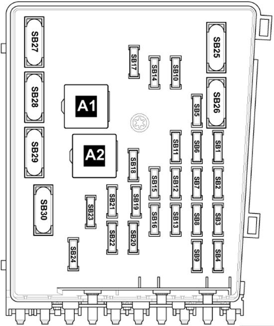
Fuses
Assignment of the fuses in engine compartment fuse box (SB) E-Box Low
| No. | Amps | Description |
|---|---|---|
| SB1 | 7.5A | Multimedia system control unit |
| SB2 | 30A | ABS control unit |
| SB3 | 20A | Treble and bass tone horn, Onboard supply control unit |
| SB4 | 20A | up to Apr 2006: Convenience system central control unit |
| 25A | from May 2006: Trailer detector control unit | |
| SB5 | 5A | Battery monitor control unit, Onboard supply control unit |
| SB6 | 5A | Automatic gearbox control unit |
| 15A | Mechatronic unit for dual clutch gearbox | |
| SB7 | 15A 20A 25A | Radio, Control unit with display for TV, radio, navigation (Japan), Control unit with display for radio and navigation system, Voltage stabiliser |
| SB8 | 30A | Mechatronic unit for dual clutch gearbox |
| SB9 | 5A | Steering column electronics control unit |
| SB10 | 20A | Fuel pump relay (diesel), Automatic glow period control unit (diesel), Ignition coils with final output stages (cylinders 1-4) |
| SB11 | 5A | Control unit in dash panel insert (start/stop system) |
| SB12 | 5A | Mobile telephone operating electronics control unit, Aerial selection control unit (up to Apr 2006), Operating unit for preparation for mobile telephone (from May 2006), TV tuner (from Nov 2008), Satellite digital radio tuner (from Nov 2008) |
| SB13 | 10A | Main relay, Terminal 30 voltage supply relay, Engine control unit |
| SB14 | 30A (diesel) 25A (petrol) | Engine control unit |
| SB15 | up to Oct 2006: 10A from Nov 2006: 5A | Data bus diagnostic interface |
| SB16 | 5A 10A | Secondary air pump relay, Exhaust gas recirculation valve (diesel), Charge pressure control solenoid valve (diesel), Turbocharger air recirculation valve (diesel), Intake manifold flap valve, Exhaust gas recirculation cooler change-over valve, Lambda probe heater, Lambda probe 2 heater |
| SB17 | 10A 40A | Fuel tank shut-off valve 1, 2, and 3, Low heat output relay (from Nov 2006) |
| SB18 | 5A 10A 30A | Low and high heat output relay (from Nov 2006), Continued coolant circulation pump, Reducing-agent heater control unit |
| SB19 | 30A | Amplifier, Special vehicles |
| SB20 | 5A 10A (engine code CBFA) 15A | Supplementary fuel pump relay, Radiator fan control unit (engine code CBAC), Automatic glow period control unit (engine code CBAC), Clutch position sender, Activated charcoal filter system solenoid valve 1, Camshaft control valve 1, Turbocharger air recirculation valve, Intake manifold flap valve, Secondary air inlet valve, Fuel pressure regulating valve |
| SB21 | 20A | Auxiliary heater control unit |
| SB22 | 30A | Wiper motor control unit |
| SB23 | 5A 10A | Magnetic field sender for compass, Automatic glow period control unit, Map-controlled engine cooling system thermostat, Radiator fan control unit, Activated charcoal filter system solenoid valve 1, Variable intake manifold change-over valve, Camshaft control valve 1, Intake manifold flap valve, Intake manifold flap motor, Lambda probe heater, Lambda probe 1 heater after catalytic converter |
| SB24 | 10A / 15A (depending on equipment) | NOx sensor control unit, Lambda probe heater, Lambda probe 1, 2, and 3 heater after catalytic converter |
| SB25 | 40A | Onboard supply control unit – Left side light bulb, Right headlight dipped and main beam bulb, Right tail light bulb (outer light ring), Left tail light bulb (inner light ring) |
| SB26 | 40A | Onboard supply control unit – Right side light bulb, Left headlight dipped and main beam bulb, Left tail light bulb (outer light ring), Right tail light bulb (inner light ring) |
| SB27 | 60A | Heated windscreen |
| SB28 | 40A | Secondary air pump motor |
| 50A | Automatic glow period control unit (diesel) | |
| SB29 | 50A | Onboard supply control unit, X-contact relief relay |
| SB30 | 50A | Onboard supply control unit |
Relays
Assignment of the relays in engine compartment fuse box (SB) E-Box Low
Additional Relay Box (1)
The additional relay carrier is located under the E-box and is only visible when the E-box is removed.
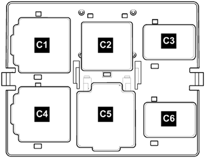
Relays
Assignment of the relays in engine compartment under the fuse box (SB)
Additional Relay Box (2)
Automatic glow period control unit.
Windshield Heater Relay
In Plenum Chamber beside Engine Control Module.
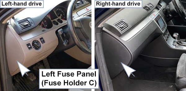
Dashboard (Left)
Fuse Box Location
Fuse Box Diagram (-SC-)
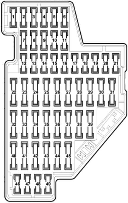
Fuses
Assignment of the fuses in the passenger compartment left side (SC)
| No. | Amps | Description |
|---|---|---|
| SC1 | 10A | up to Apr 2008: Diagnosis connection |
| 10A | from May 2008: Rear roller blind switch, Rear roller blind motor | |
| SC2 | 5A | TCS and ESP button, AUTOHOLD button from May 2008: ABS control unit, Control unit for electromechanical parking brake |
| SC3 | 5A | Power steering control unit from May 2008: Lighting switch, Brake light switch, Oil level and oil temperature sender |
| SC4 | 5A | up to Apr 2008: Brake light switch |
| 5A | from May 2008: Electronically controlled damping control unit, Trailer detector control unit, Control unit for bend lighting and headlight range control, Diagnosis connection | |
| SC5 | 10A | up to Apr 2008: Headlight range control regulator, Power output module for left headlight, Left headlight range control motor, Right headlight range control motor |
| 10A | from May 2008: Switch and instrument illumination regulator, Headlight range control regulator, Power output module for left headlight, Left headlight range control motor | |
| SC6 | 5A | up to Apr 2008: Trailer detector control unit |
| 10A | from May 2008: All-wheel drive control unit | |
| SC7 | 5A | Control unit in dash panel insert, Data bus diagnostic interface |
| SC8 | 5A | up to Apr 2008: Rear roller blind switch (up to May 2005), Garage door operating unit (up to May 2005), Rear roller blind control unit (up to May 2005), Automatic anti-dazzle interior mirror |
| 10A | from May 2008: Power output module for right headlight, Right headlight range control motor | |
| SC9 | 10A | up to Apr 2008: All-wheel drive control unit |
| 10A | from May 2008: Airbag control unit, Seat occupied recognition control unit, Front passenger side airbag deactivated warning lamp | |
| SC10 | 5A | up to Apr 2008: Main relay, Engine control unit, Motronic current supply relay 2 |
| 10A | from May 2008: Tiptronic switch, Air mass meter, Fuel pump control unit, Main relay, Engine control unit, Motronic current supply relay 2 | |
| SC11 | 5A | Crash data recorder button (Police), Taximeter (Taxi), Mirror taxi meter (Taxi), Crash data recorder, Tachograph coupling point (Police), Special signal system coupling point (Police), Warning buzzer for pedal switch on front passenger side (Driving school) |
| SC12 | 10A | up to Apr 2008: Driver door control unit, Rear right door control unit (from May 2006) |
| 10A | from May 2008: Driver door control unit, Front passenger door control unit | |
| SC13 | 10A | Lighting switch, Diagnosis connection from May 2008: Tiptronic switch |
| SC14 | 5A | up to Apr 2008: Electronic steering column lock control unit |
| 10A | from May 2008: Alarm horn relay (USA and Canada), Alarm horn | |
| SC15 | 5A | Onboard supply control unit (30g), Front interior light from May 2008: Interior monitor send and receive module 1 |
| SC16 | 10A | Electronic ignition lock from May 2008: Electronic steering column lock control unit |
| SC17 | 10A | up to Apr 2008: Interior monitor send and receive module 1, Rain and light sensor, Vehicle inclination sender, Alarm horn, Remote control receiver for auxiliary coolant heater |
| 5A | from May 2008: Electromechanical parking brake button, ABS control unit | |
| SC18 | – | up to Apr 2008: Not Assigned |
| 10A | from May 2008: Heater element for crankcase breather (cold-climate countries) | |
| SC19 | – | up to Apr 2008: Not Assigned |
| 7.5A | from May 2008: Adaptive cruise control unit, Parking aid control unit, Lane departure warning control unit, Park assist steering control unit | |
| SC20 | – | up to Apr 2008: Not Assigned |
| 5A | from May 2008: Garage door operating unit (not right-hand drive) | |
| SC21 | – | up to Apr 2008: Not Assigned |
| 10A | from May 2008: Automatic anti-dazzle interior mirror, Heated rear left and right seat switch with regulator, High-pressure sender, Air quality sensor, Fresh air blower relay, Left and right washer jet heater element, Air conditioning system control unit, Voltage monitoring relay (RSE Multimedia system) | |
| SC22 | 10A 5A | up to Apr 2008: Air mass meter, Electric fuel pump 2 relay |
| 20A | from May 2008: Control unit for electromechanical parking brake | |
| SC23 | 10A | up to Apr 2008: Heater element for crankcase breather (cold-climate countries) |
| 15A | from May 2008: Trailer detector control unit | |
| SC24 | 5A 20A (automatic gearbox) | up to Apr 2008: Reversing light switch, Multifunction switch, Automatic gearbox control unit, Mechatronic unit for dual clutch gearbox |
| 20A | from May 2008: Control unit for electromechanical parking brake | |
| SC25 | 10A | up to Apr 2008: Injectors (up to Nov 2005), Garage door operating unit (up to Apr 2006) |
| 20A | from May 2008: Trailer detector control unit | |
| SC26 | 10A | up to Apr 2008: Rear roller blind switch (from May 2005), Rear roller blind control unit (from May 2005) |
| 15A | from May 2008: Electronically controlled damping control unit | |
| SC27 | 5A | up to Apr 2008: Fresh air blower relay (Climatic with supplementary coolant heater), Climatronic control unit (no supplementary coolant heater) |
| 15A (petrol) 20A (diesel) | from May 2008: Fuel pump relay (diesel), Electric fuel pump 2 relay (diesel), Fuel pump control unit (petrol), Relay for supplementary fuel pump (diesel) | |
| SC28 | 20A | up to Apr 2008: Trailer detector control unit (from May 2006) |
| 10A | from May 2008: Rear left and right door control unit, Convenience system central control unit | |
| SC29 | 20A | up to Apr 2008: Trailer detector control unit – left tail light, brake light, right/left turn signal (up to Apr 2006) Control unit for electromechanical parking brake (from May 2006) |
| 25A | from May 2008: Heated rear seats control unit | |
| SC30 | 15A | up to Apr 2008: Trailer detector control unit – right tail light, rear fog light, reversing lights (up to Apr 2006) Control unit for electromechanical parking brake (from May 2006) |
| 20A | from May 2008: Sliding sunroof control unit | |
| SC31 | 25A 15A (from Nov 2006) | up to Apr 2008: Trailer detector control unit (up to Apr 2006), Fuel pump relay, Electric fuel pump 2 relay, Fuel pump control unit (from Nov 2006) |
| 30A | from May 2008: DC/AC converter with socket, 12V-230V, Converter with socket, 12V-115V (USA) | |
| SC32 | 30A | Onboard power supply control unit (heated rear window) |
| SC33 | 20A | up to Apr 2008: Sliding sunroof control unit |
| 30A | from May 2008: Headlight washer system relay, Headlight washer system pump | |
| SC34 | 15A | up to Apr 2008: Fuel system pressurisation pump |
| 25A | from May 2008: Heated front seats control unit | |
| SC35 | 30A 25A (from Nov 2006) | up to Apr 2008: Headlight washer system relay, Headlight washer system pump |
| 30A | from May 2008: Rear left and right door control unit | |
| SC36 | 20A | up to Apr 2008: Auxiliary heater operation relay (not with Climatronic) |
| 15A | from May 2008: Driver seat lumbar support adjustment switch, Rake adjustment button, Backrest adjustment button | |
| SC37 | 25A | up to Apr 2008: Heated front seats control unit |
| 10A | from May 2008: Magnetic field sender for compass, Rain and light sensor, Climatronic control unit, Air conditioning system control unit, Reversing camera system control unit, Remote control receiver for auxiliary coolant heater, Voltage monitoring relay (RSE Multimedia system) | |
| SC38 | 15A | up to Apr 2008: Trailer detector control unit (from May 2006), Cigarette lighter (up to Apr 2006), Rear cigarette lighter (up to Apr 2006) |
| 40A | from May 2008: Fresh air blower relay, Fresh air blower control unit (Climatronic), Air conditioning system control unit (Climatic) | |
| SC39 | 40A | up to Apr 2008: Fresh air blower control unit (Climatronic), Air conditioning system control unit |
| 15A (6-speed auto) 5A | from May 2008: Multifunction switch (6-speed auto), Automatic gearbox control unit (6-speed auto), Reversing light switch, Mechatronic unit for dual clutch gearbox | |
| SC40 | 5A | up to Apr 2008: Lighting switch |
| 15A | from May 2008: Second battery charging circuit relay, Washer pump, Rear window wiper motor | |
| SC41 | 40A (up to Apr 2006) 15A | up to Apr 2008: Fresh air blower (up to Apr 2006), Fresh air blower relay (up to Apr 2006), Cigarette lighter (from May 2006), Rear cigarette lighter (from May 2006) |
| 20A | from May 2008: Cigarette lighter (diesel), Rear cigarette lighter (diesel) | |
| SC42 | 15A | up to Apr 2008: Windscreen and rear window washer pump, Rear window wiper motor |
| 15A | from May 2008: 12V socket | |
| SC43 | 20A | Auxiliary heater control unit (with auxiliary battery from May 2008) |
| SC44 | 20A | up to Apr 2008: Auxiliary heater operation relay |
| 30A | from May 2008: Driver door control unit, Front passenger door control unit | |
| SC45 | 25A | up to Apr 2008: 12V socket, 12V socket 3 (Taxi from May 2005) |
| 20A | from May 2008: Auxiliary heater operation relay (with auxiliary battery) | |
| SC46 | 5A | up to Apr 2008: 2-way radio unit switch, Engine continues to run with no key button, Crash data recorder, Tachograph coupling point |
| – | from May 2008: Not Assigned | |
| SC47 | 15A | up to Apr 2008: Taxi equipment (Taxi meter, Mirror taxi meter, Taxi roof sign warning lamp, Interior light warning lamp, Taxi silent alarm bulb, Alarm button illumination lamp, Glove and Luggage compartment coupling points), Police equipment (Luggage compartment light on left, Two-way radio coupling point) |
| 10A | from May 2008: Telephone transmitter and receiver unit (start/stop system) | |
| SC48 | 20A | up to Apr 2008: Charger coupling point (Police) |
| 5A | from May 2008: Control unit in dash panel insert (start/stop system) | |
| SC49 | – | – |
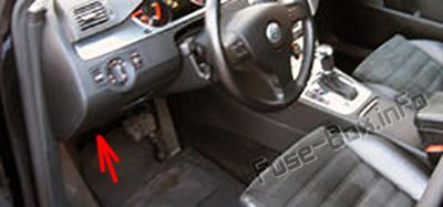
Dashboard (Right)
Fuse Box Location
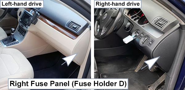
Fuse Box Diagram (-SD-)
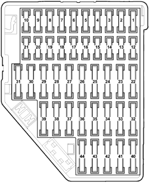
Fuses
Assignment of the fuses in the passenger compartment right side (SD)
| No. | Amps | Description |
|---|---|---|
| SD1 | 5A | from May 2005: Magnetic field sender for compass |
| SD2 | 5A | Control unit for electromechanical parking brake, ABS control unit |
| SD3 | 5A | Parking aid control unit up to Apr 2006: Magnetic field sender for compass |
| SD4 | 5A | Adaptive cruise control unit |
| SD5 | 10A | Power output module for right headlight (gas discharge headlights) |
| SD6 | 5A | Tiptronic switch |
| SD7 | 5A | Control unit for cornering light and headlight range control (gas discharge headlamp) |
| SD8 | 5A | High-pressure sender, Oil level and oil temperature sender |
| SD9 | 10A | Front passenger side airbag deactivated warning lamp, Airbag control unit, Seat occupied recognition control unit |
| SD10 | 5A | Fuel pump control unit (engine codes BLF, BLR, BLY, AXX, BPY, BLX, BVX, BVY, BVZ, BWA) |
| SD11 | – | – |
| SD12 | 10A | Front passenger door control unit up to Apr 2006: Rear right door control unit |
| SD13 | 10A | up to Apr 2006: Parking aid control unit |
| SD14 | 5A | from Nov 2007: Reversing camera system control unit |
| SD15 | 5A | Climatronic control unit, Air conditioning system control unit |
| SD16 | 5A | Tiptronic switch |
| SD17 | 5A | Electromechanical parking brake warning lamp, ABS control unit |
| SD18 – SD21 | – | – |
| SD22 | 30A | DC/AC converter with socket, 12V-230V, Converter with socket, 12V-115V (American markets) |
| SD23 | 30A | Rear left and right door control unit |
| SD24 | 30A | Power latching control unit for rear left door (Variant) |
| SD25 | 30A | Power latching control unit for rear right door (Variant) |
| SD26 | – | – |
| SD27 | 25A | Heated rear seats control unit |
| SD28 | 15A | up to Apr 2006: Fuel pump control unit (engine codes AXZ, BLV) |
| SD29 | 30A | Driver and front passenger door control unit |
| SD30 | 20A | up to Apr 2006: Control unit for electromechanical parking brake |
| 20A | May 2006 to Oct 2006: Convenience system central control unit | |
| SD31 | 20A | up to Apr 2006: Control unit for electromechanical parking brake |
| 15A | May 2006 to Oct 2006: Fuel pump control unit | |
| SD32 | – | – |
| SD33 | 20A | up to Apr 2006: 12V socket 1 and 2 |
| SD34 | 15A | up to Apr 2006: Fuel pump control unit (engine codes AXX, BPY, BLF, BLR, BLY, BLX, BVX, BVY, BVZ, BWA) |
| SD35 | 20A | up to Apr 2006: Cigarette lighter, Rear cigarette lighter |
| SD36 – SD37 | – | – |
| SD38 | 15A | from May 2006: 12V socket |
| SD39 | 10A | Climatronic control unit, Air conditioning system control unit, Second battery charging circuit relay, Left and right washer jet heater element up to Apr 2006: Heated driver and front passenger seat regulator, Heated rear left and right seat switch with regulator |
| SD40 | 5A | up to Apr 2005 (Taxi): Crash data recorder |
| SD41 | 15A | up to Apr 2005 (Taxi): Taxi meter, Mirror taxi meter, Taxi roof sign warning lamp, Interior light warning lamp, Alarm button illumination lamp, Glove and luggage compartment coupling points |
| SD42 | 20A | up to Apr 2005 (Taxi): Glove compartment coupling point |
| SD43 | 5A | Special signal system coupling point (Police) up to Apr 2005 (Taxi): Control unit for taxi alarm remote control from May 2005 (Taxi): Glove and luggage compartment coupling points |
| SD44 | 10A | Special signal system coupling point (Police) up to Apr 2005 (Taxi): 12V socket 3 from May 2005 (Taxi): Control unit for taxi alarm remote control |
Relay Carriers
Relay Box Locations
Under dashboard on the driver side.
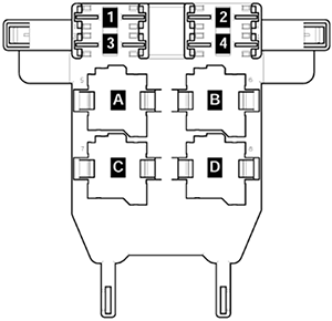
Relay Box (1) Diagram
Fuses
Assignment of the fuses in the passenger compartment relay box No.1
Relays
Assignment of the relays in the passenger compartment relay box No.1
| No. | Description |
|---|---|
| 1 | Auxiliary heater operation relay -J485- (53) (Only Climatic) |
| Voltage monitoring relay -J813- (Only with Multimedia RSE) | |
| 2 | Continued coolant circulation relay -J151- (449) (only for 1.8L / 2.0L TFSI and 1.4L BiTFSI) |
| Electric fuel pump 2 relay -J49- (449) (Only for Common-rail diesel engines) | |
| Current supply relay -J16- (449) (applicable from May 2009) (Only 6-cylinder petrol engines and 1.6L / 77 kW Common Rail diesel) | |
| 3 | Fresh air blower relay -J13- (404), from May 2008 (449) (only auxiliary coolant heater) |
| 4 | Fuel pump relay -J17- (404), from May 2008 (449) |
| 5 | Electric fuel pump 2 relay -J49- (404), from May 2008 (449) |
| 6 | Headlight washer system relay -J39- (53) |
| 7 | Terminal 50 voltage supply relay -J682- (433), from November 2006 (53) |
| Terminal 50 voltage supply relay -J682- (433) (Only vehicles with 0GT emissions standard from November 2009) |
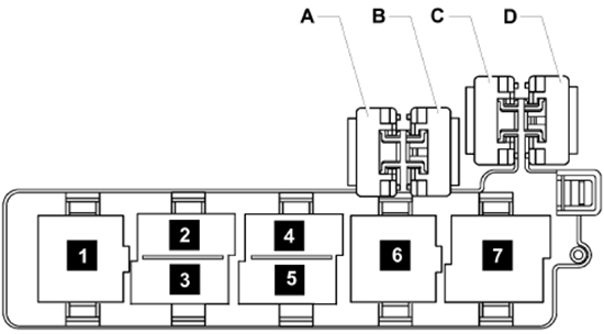
Relay Box (2) Diagram
On Vehicle Electrical System Control Module, in Driver’s Footwell.
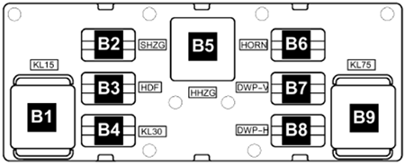
Relays
Assignment of the relays in the passenger compartment relay box No.2
| No. | Description |
|---|---|
| B1 | Terminal 15 voltage supply relay -J329- (460) |
| B2 | – |
| B3 | – |
| B4 | Terminal 30 voltage supply relay 2 -J689- (449) |
| B5 | Heated rear window relay -J9- (53) |
| B6 | Dual tone horn relay -J4- (449) |
| B7 | Double washer pump relay 1 -J729- (404) |
| B8 | Double washer pump relay 2 -J730- (404) |
| B9 | X-contact relief relay -J59- (460) |
Relay Box (3) Diagram
Under instrument panel, left.
Relays
Assignment of the relays in the passenger compartment relay box No.3
Luggage Compartment
Fuse Box Location
The fuses are located near the battery in luggage compartment behind left side panel trim (engines AXZ, BLV, BWS).
Fuse Box Diagram (-SF-)
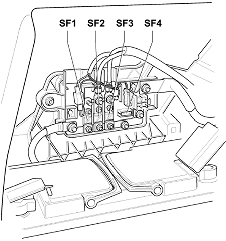
High Voltage Fuses
Assignment of the high voltage fuses in the luggage compartment fuse box (SF)
Additional Fuse
70A – Saloon / 60A – Variant