Looking for Volkswagen Passat fuse box diagrams? This article covers the Volkswagen Passat (Model Code: A34) for the North American market, produced from 2019 to 2022, and includes fuse box diagrams for Volkswagen Passat (A34) 2019, 2020, 2021 and 2022, along with details about the location of the fuse panels inside the vehicle and a clear explanation of the assignment of each fuse and relay (fuse layout).
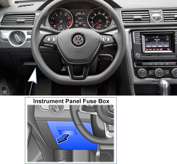
Open the storage compartment on the driver’s side in the direction of the arrow. Use some force to pull the storage compartment back and out of the mounts. Plastic pliers for pulling out fuses can be found on the inside of the cover.
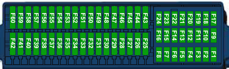
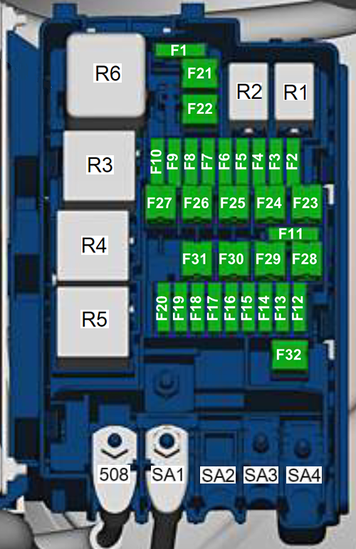
Fuse Box Diagram
Fuses
Assignment of the fuses in the passenger compartment
Fuse Data
Full access is available to registered users — log in or register.
Electronic steering column lock control module -J764-
SC2
–
–
SC3
5A
Instrument cluster -KX2- – Instrument cluster control module -J285-
SC4
5A
Control module for emergency call module and communication unit -J949-
SC5
–
SC6
10A
Rear lid handle -EX37- – Rearview camera -R189-
SC7
–
–
SC8
–
–
SC9
5A
Airbag control module -J234- Passenger occupant detection system control module -J706- Front passenger airbag -disabled- indicator lamp -K145- Terminal 15 relay -J940-
SC10
10A
USB charging socket 1 -U37-
SC11
10A
Left Front Headlamp -MX1-
SC12
20A
Right Front Headlamp -MX2-
SC13
10A
Automatic dimming interior rearview mirror -Y7- Parking aid control module -J446- Rear seat heating control module -J786- High pressure sensor -G65- Adaptive Cruise Control Sensor -G550- Tire pressure monitoring display button -E492- Back-Up Lamp Switch -F4- Distance regulation control module -J428- Headlamp range control module -J431-
SC14
10A
Instrument cluster -KX2- – Instrument cluster control module -J285- Oil level thermal sensor -G266- Power steering control module -J500- Data bus on board diagnostic interface -J533- ABS control module -J104-
Ignition Coil 1 with Power Output Stage -N70- Ignition Coil 2 with Power Output Stage -N127- Ignition Coil 3 with Power Output Stage -N291- Ignition Coil 4 with Power Output Stage -N292-
SB13
–
–
SB14
10A
Engine control module -J623- Motronic engine control module power supply relay -J271- Driver windshield wiper motor -V216- Wiper motor relay 2 -J369- Wiper motor relay 1 -J368-
SB15
30A
ABS control module -J104-
SB16
40A
Vehicle electrical system control module -J519-
SB17
15A
Transmission control module -J217-
SB18
40A
Vehicle electrical system control module -J519-
SB19
5A
Vehicle electrical system control module -J519-
SB20
30A
Driver windshield wiper motor -V216- Wiper motor relay 2 -J369-
SB21
40A (2.5L) 50A (2.0L)
Secondary air injection pump motor -V101-
SB22
–
–
SB23
40A
Tehminal 75 Power Supply Relay 1 -J680-
SB24
–
–
SB25
40A
Terminal 15 relay -J940-
SB26
–
–
SB27
50A
Radiator fan -VX57-
SB28
–
–
SB29
–
–
SB30
60A
ABS control module -J104-
SB31
40A
Amplifier -R12-
SB32
–
–
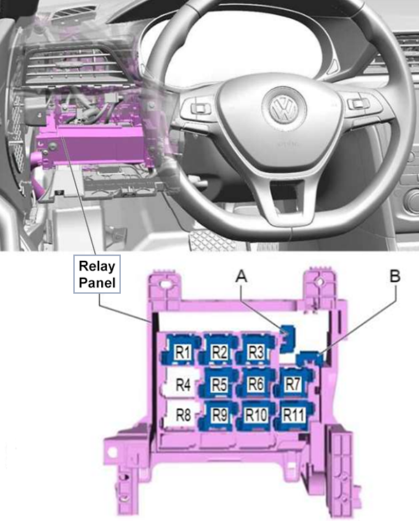
Relays
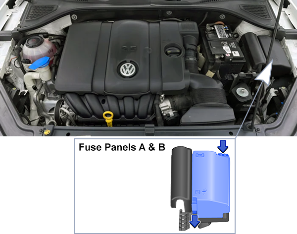
Assignment of the relays in the engine compartment
Fuse Data
Full access is available to registered users — log in or register.
")
")
")
")
")
")